Magnetic resonance system and operating method therefor

Active Publication Date: 2015-12-24
SIEMENS HEALTHCARE GMBH
View PDF8 Cites 5 Cited by
  • Summary
  • Abstract
  • Description
  • Claims
  • Application Information

AI Technical Summary

Benefits of technology

[0010]An object of the present invention is to provide a method for op

Problems solved by technology

In such cases, it is a problem that searching for the correct measureme

Method used


Image

  • Magnetic resonance system and operating method therefor
  • Magnetic resonance system and operating method therefor
  • Magnetic resonance system and operating method therefor

Examples


Embodiment Construction

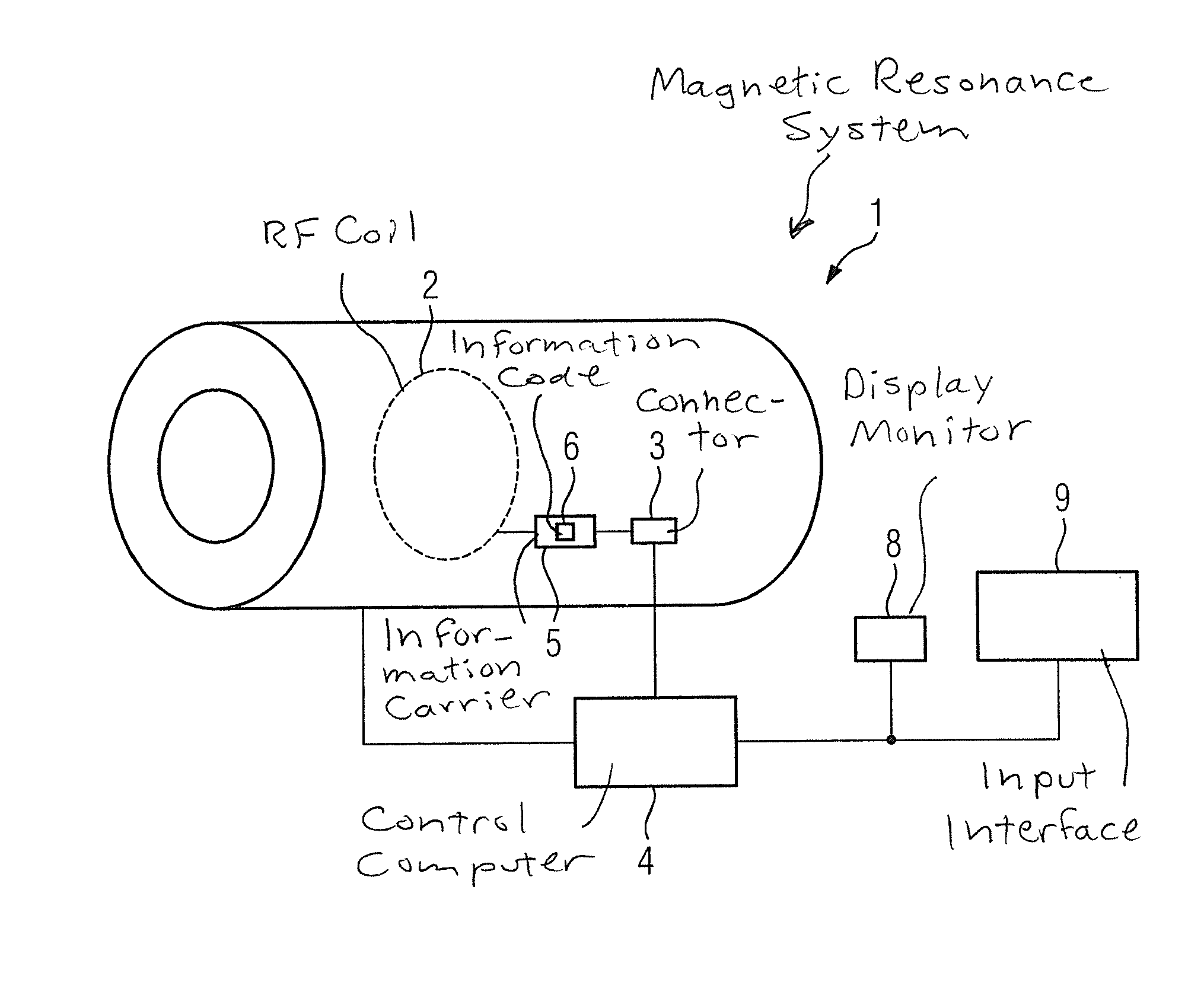
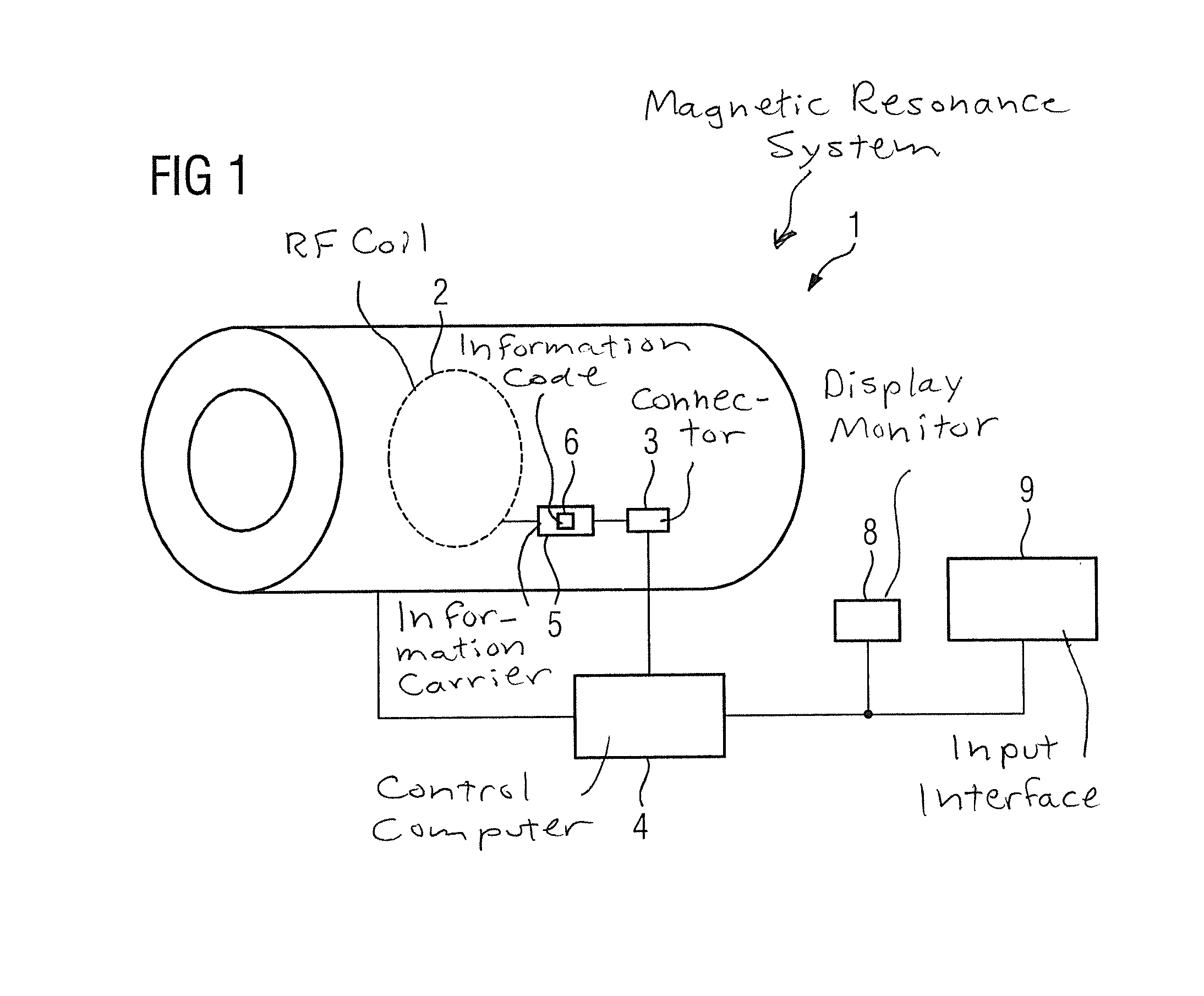
[0043]FIG. 1 shows a magnetic resonance system 1 that has a scanner with at least one radio-frequency (RF) coil 2. The radio-frequency coil 2 is connected via a connector 3 to the control computer 4 that operates the scanner of magnetic resonance system 1, wherein the connector 3 makes an electrical connection possible. The connector 3 can be embodied as a plug-in connection. The connector 3 makes it possible to connect various radio-frequency coils 2 to the control computer 4. This diagram is naturally simplified, more elements than the connector 3 are of course located between the radio-frequency coil 2 and the control computer 4 of the magnetic resonance system 1. The connector is important since it allows the exchange of different radio-frequency coils 2.

[0044]The radio-frequency coil 2 has an information carrier 5, which bears an information code 6. This information code 6 is coil identification information. For example the identification code 6 consists of a sequence of digits su


PUM


Abstract

In a magnetic resonance (MR) apparatus and an operating method therefor, the scanner of the MR apparatus has at least one connector for connecting a radio-frequency coil, as well as a control computer with a display screen. Connection of a radio-frequency coil to the connector causes at least one item of coil identification information, and selection of at least one measurement protocol from among a number of measurement protocols for recording magnetic resonance signals with the connected coil to be made by the control computer as a function of the at least one item of coil identification information.

Description


Claims


Application Information

Patent Timeline
Owner SIEMENS HEALTHCARE GMBH
Why Eureka
Try Eureka