Liquid crystal display apparatus

Active Publication Date: 2016-05-26
TRIVALE TECH
View PDF4 Cites 7 Cited by
  • Summary
  • Abstract
  • Description
  • Claims
  • Application Information

AI Technical Summary

Benefits of technology

[0009]It is an object of the present invention to provide a liquid crystal display apparatus that suppresses occurrence of display unevenness during a lighting inspection by a collective drive control.

Problems solved by technology

Upsizing and high resolution of a display panel in recent times causes distribution of a wiring resistance in a display plane, resulting in occurrence of display unevenness during the inspection by the collective control.
However, when wires in a collective drive inspection circuit are different from the plurality of wires to which the above-mentioned technique is applied, the display unevenness caused by the distribution of the wiring resistance may occur during the collective drive even in the display panel in which the display unevenness is prevented during the normal drive.
In other words, the common wire portion causes the distribution of the wiring resistance in the collective drive inspection circuit, so that the display unevenness fails to be improved by individually adjusting the wires as proposed in Japanese Patent Application Laid-Open No. 2000-187451.

Method used


Image

  • Liquid crystal display apparatus
  • Liquid crystal display apparatus
  • Liquid crystal display apparatus

Examples


Example

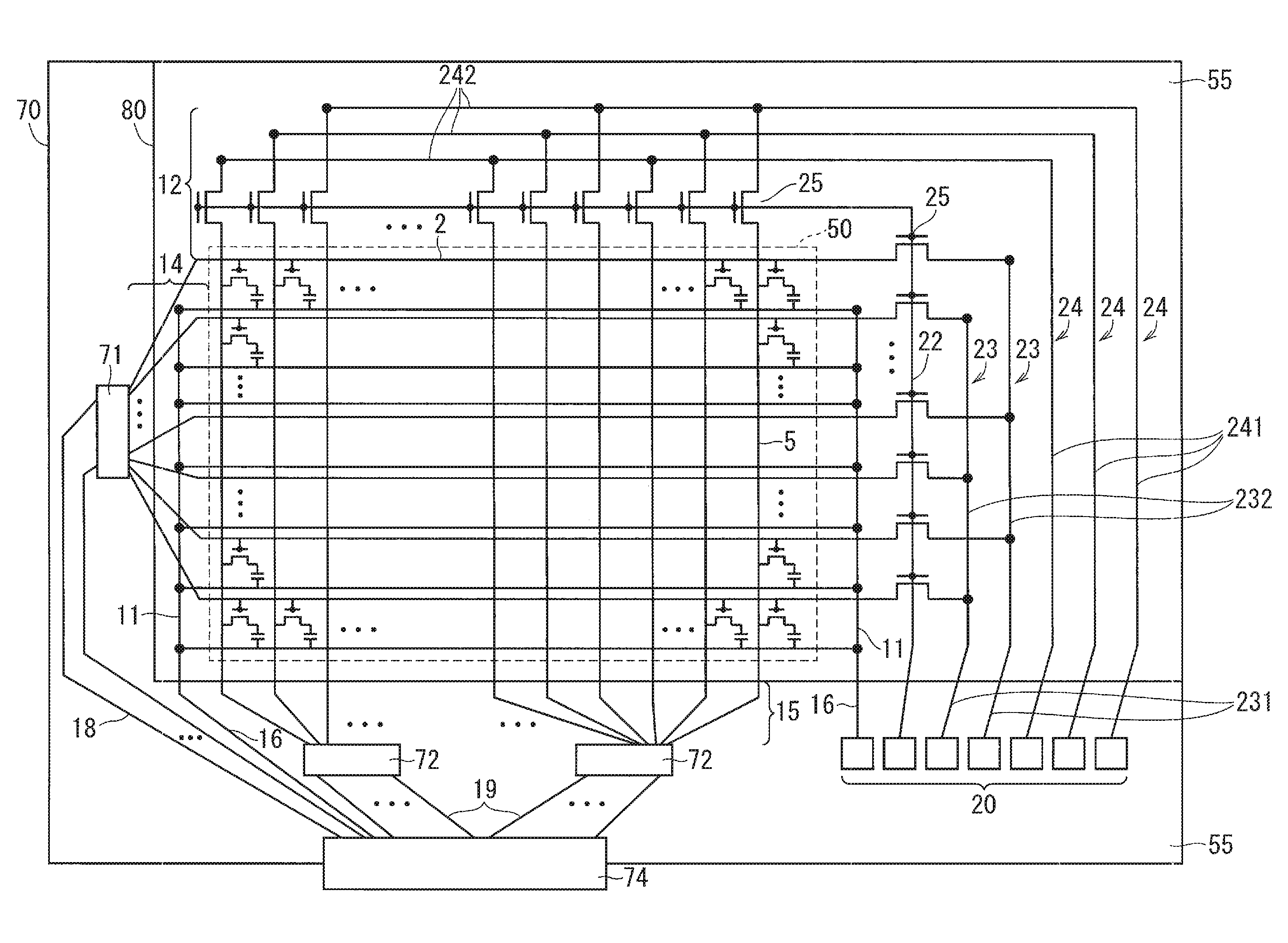
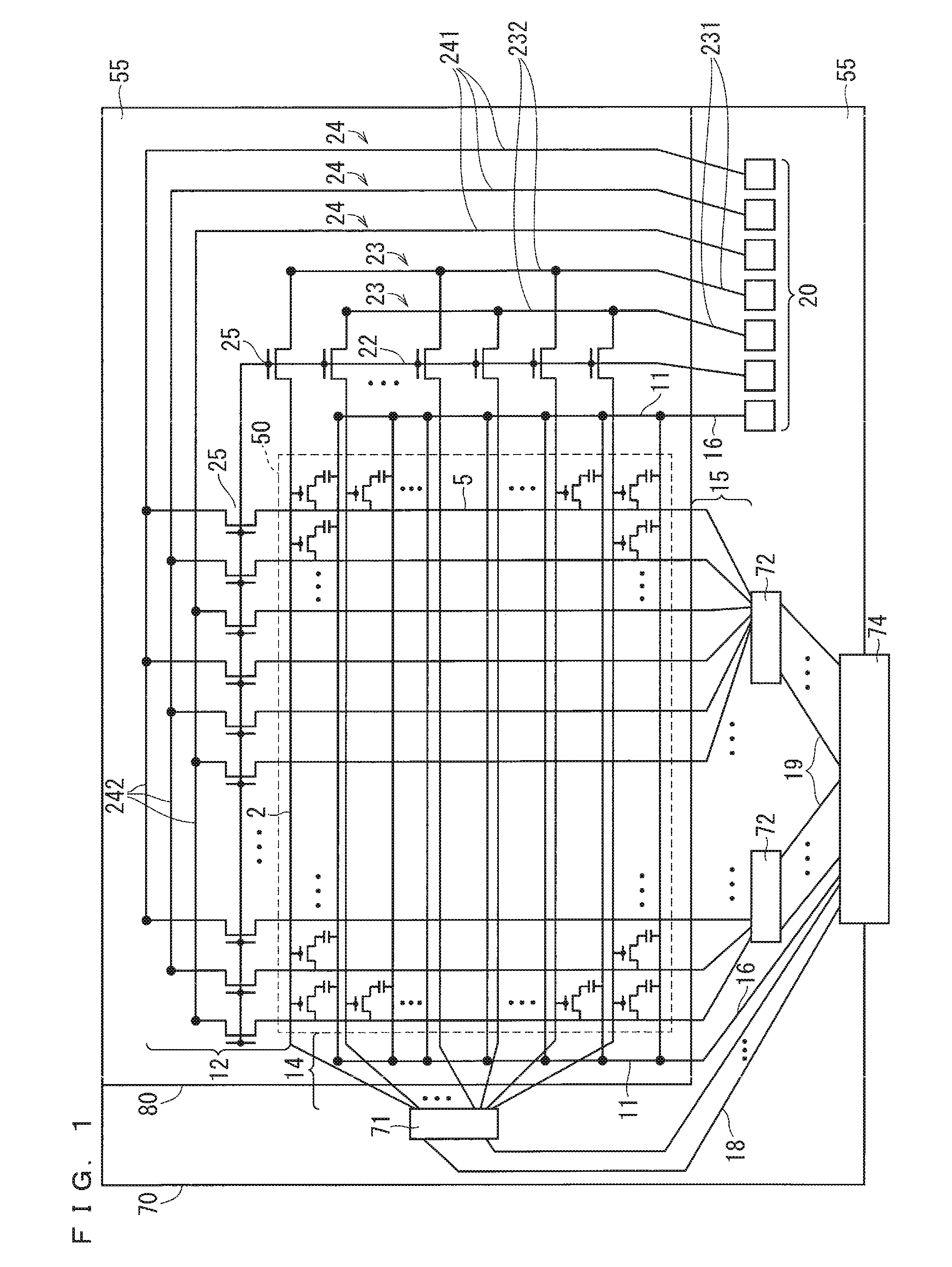
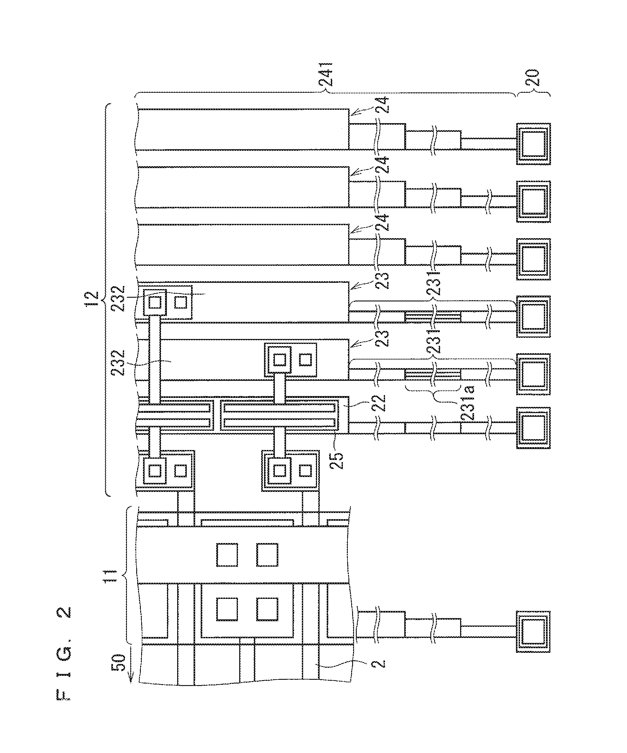
[0020]FIG. 1 is a plan view showing a configuration of a liquid crystal display apparatus according to a first preferred embodiment. FIG. 2 is a partially enlarged view of a collective drive lighting inspection circuit 12 of the liquid crystal display apparatus according to the first preferred embodiment. The same or similar components of display devices according to other preferred embodiments are denoted by the same references of the components of the liquid crystal display apparatus according to the first preferred embodiment shown in FIG. 1.

[0021]As shown in FIG. 1, a plurality of pixels being display units of an image are provided in a display region 50 indicated by dotted lines. A thin film transistor (TFT) being a switching element that supplies display voltage to a pixel electrode is disposed in each of the pixels. A member formed of a substrate on which the TFTs are mounted is referred to as a TFT array substrate 70. The TFT array substrate 70 includes the TFTs in each of the


PUM


Abstract

A liquid crystal display apparatus includes a collective drive lighting inspection signal input wire that electrically connects a collective drive lighting inspection terminal to a plurality of gate wires and a plurality of source wires. The collective drive lighting inspection signal input wire includes a first wire corresponding to the gate wires and a second wire corresponding to the source wires. The first wire and the second wire each include a connection wire and a lead-out wire. The connection wire includes branch points connected to each of the plurality of gate wires or each of the plurality of source wires. The lead-out wire is led out from the connection wire to the collective drive lighting inspection terminal. The lead-out wire included in the first wire or the second wire includes a high-resistance region having a resistivity greater than a resistivity of the connection wire connected to the lead-out wire.

Description


Claims


Application Information

Patent Timeline
Owner TRIVALE TECH
Why Eureka
Try Eureka