Powertrain mechanism with drive plate

Active Publication Date: 2016-11-03
VALEO OTOMOTIV SANAYI & TICARET AS
View PDF3 Cites 3 Cited by
  • Summary
  • Abstract
  • Description
  • Claims
  • Application Information

AI Technical Summary

Benefits of technology

[0006]The present invention relates to a powertrain mechanism, for eliminating the above

Problems solved by technology

However, in practice, it is not possible that the engine shaft and the gearbox shaft are provided in an accurately coaxial manner.
This ma

Method used


Image

  • Powertrain mechanism with drive plate
  • Powertrain mechanism with drive plate
  • Powertrain mechanism with drive plate

Examples


Embodiment Construction

)

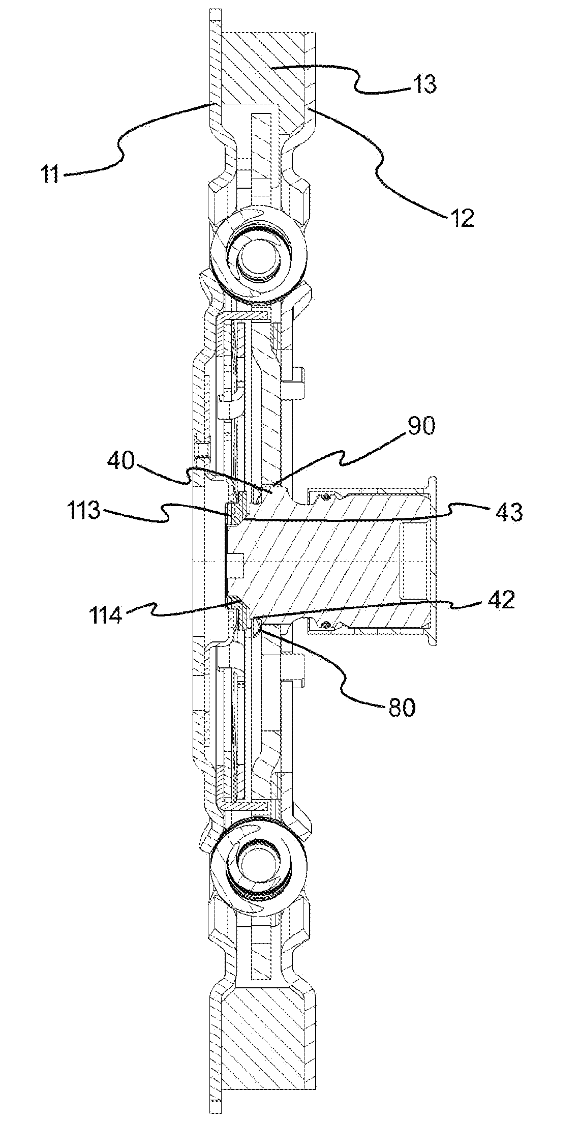
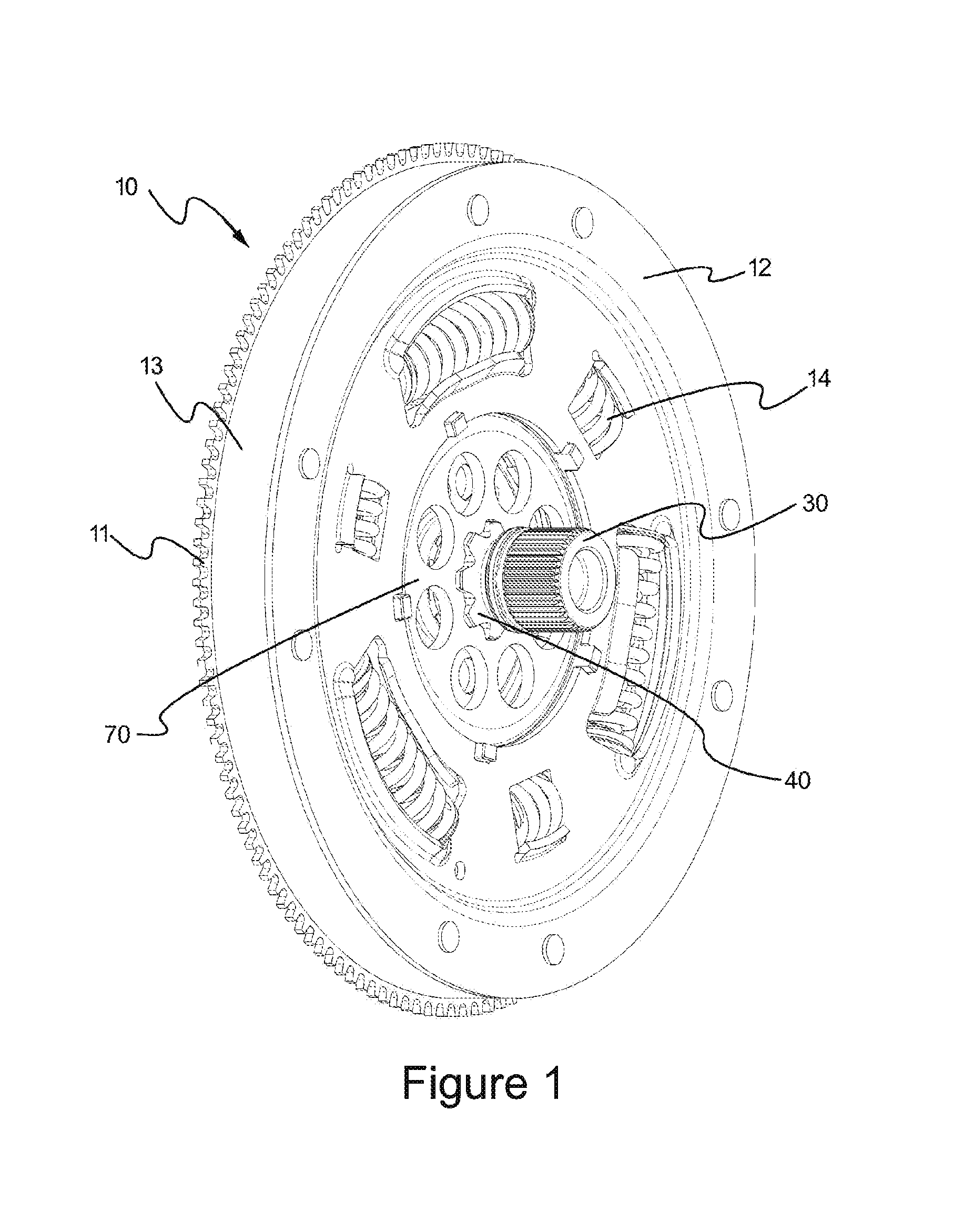
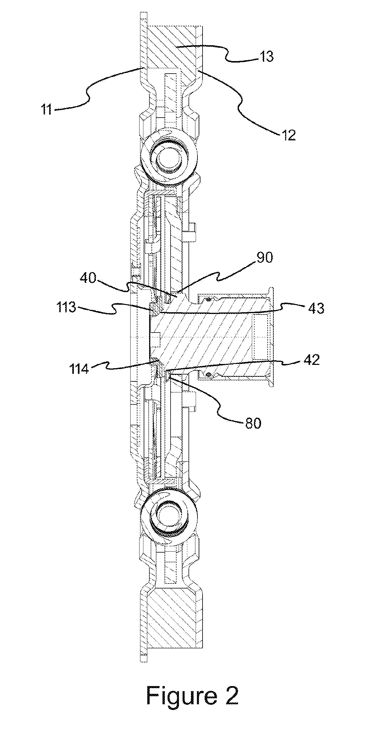
[0025]In this detailed description, the subject matter powertrain mechanism (10) is explained with references to examples without forming any restrictive effect only in order to make the subject more understandable.

[0026]As can be seen in FIGS. 1 and 2, the subject matter powertrain mechanism (10) comprises at least one inertia plate (40) positioned between a holder plate (11) and a fixation plate (12). There is at least one drive plate (70) positioned in a movable manner between said holder plate (11) and said fixation plate (12). Said drive plate (70) is connected to the holder plate (11) and to the fixation plate (12) by using at least one spring (14). The holder plate (11) is connected to the engine shaft (not illustrated in the figure). The drive plate (70) is connected to the gearbox shaft (not illustrated in the figure) by means of a connection hub (30). Thus, the holder plate (11) and the fixation plate (12) are rotated by means of the movement applied by the engine, and the m


PUM


Abstract

A powertrain mechanism (10) in order to transfer the power, received from the engine, to the gearbox in vehicles having internal combustion engine and comprising at least one drive plate (70) and at least one connection hub (30) having an assembly section (40) placed into at least one assembly opening (71) provided in vicinity of the center of the drive plate (70). As an improvement, the subject matter powertrain mechanism (10) comprises at least one movement gap (90) provided between at least one protrusion upper section (51) defined at the uppermost section of at least one protrusion (50) provided mutually on inner wall (72) of the assembly opening (71) and on outer wall (41) of the assembly section (40), and at least one recess base (61) defined at the lowermost section of at least one recess (60) wherein the protrusion (50) is at least partially placed.

Description


Claims


Application Information

Patent Timeline
Owner VALEO OTOMOTIV SANAYI & TICARET AS
Why Eureka
Try Eureka