Device for changing anode inlet and anode outlet of fuel cell stack

a technology of fuel cell stack and anode outlet, which is applied in the direction of transportation hydrogen technology, climate sustainability, electric hydrogen generators, etc., can solve the problems of fuel cell shutdown, increased leakage amount of hydrogen discharged to the outside through the purge valve, and fuel efficiency degradation, so as to improve the stability of initial fuel cell start-up and fuel efficiency, the effect of minimizing the quantity of hydrogen discharged to the outsid

Active Publication Date: 2016-11-03
HYUNDAI MOTOR CO LTD
View PDF2 Cites 0 Cited by
  • Summary
  • Abstract
  • Description
  • Claims
  • Application Information

AI Technical Summary

Benefits of technology

The technical effect of this patented technology is that it allows for better control over the amount of hydrogen supplied during startup of a fuel cell system by adjusting the direction of hydrogen supply from one side to another. This helps improve the performance and lifespan of the fuel cells while reducing their potential negative impact on the environment.

Problems solved by technology

This patent describes a method for controlling the hydrogen concentration in a fuel cell stack in response to startup conditions such as starting up the fuel cell stack under specific conditions. However, this can lead to unstable performance and increased emissions when the hydrogen purification process is completed too early.

Method used


Image

  • Device for changing anode inlet and anode outlet of fuel cell stack
  • Device for changing anode inlet and anode outlet of fuel cell stack
  • Device for changing anode inlet and anode outlet of fuel cell stack

Examples


Embodiment Construction

[0040]Hereinafter reference will now be made in detail to various embodiments of an electro-hydraulic brake system and a method for controlling the same of the present disclosure, examples of which are illustrated in the accompanying drawings and described below.

[0041]Hereinafter, exemplary embodiments of the present inventive concept will be described with reference to the accompanying drawings.

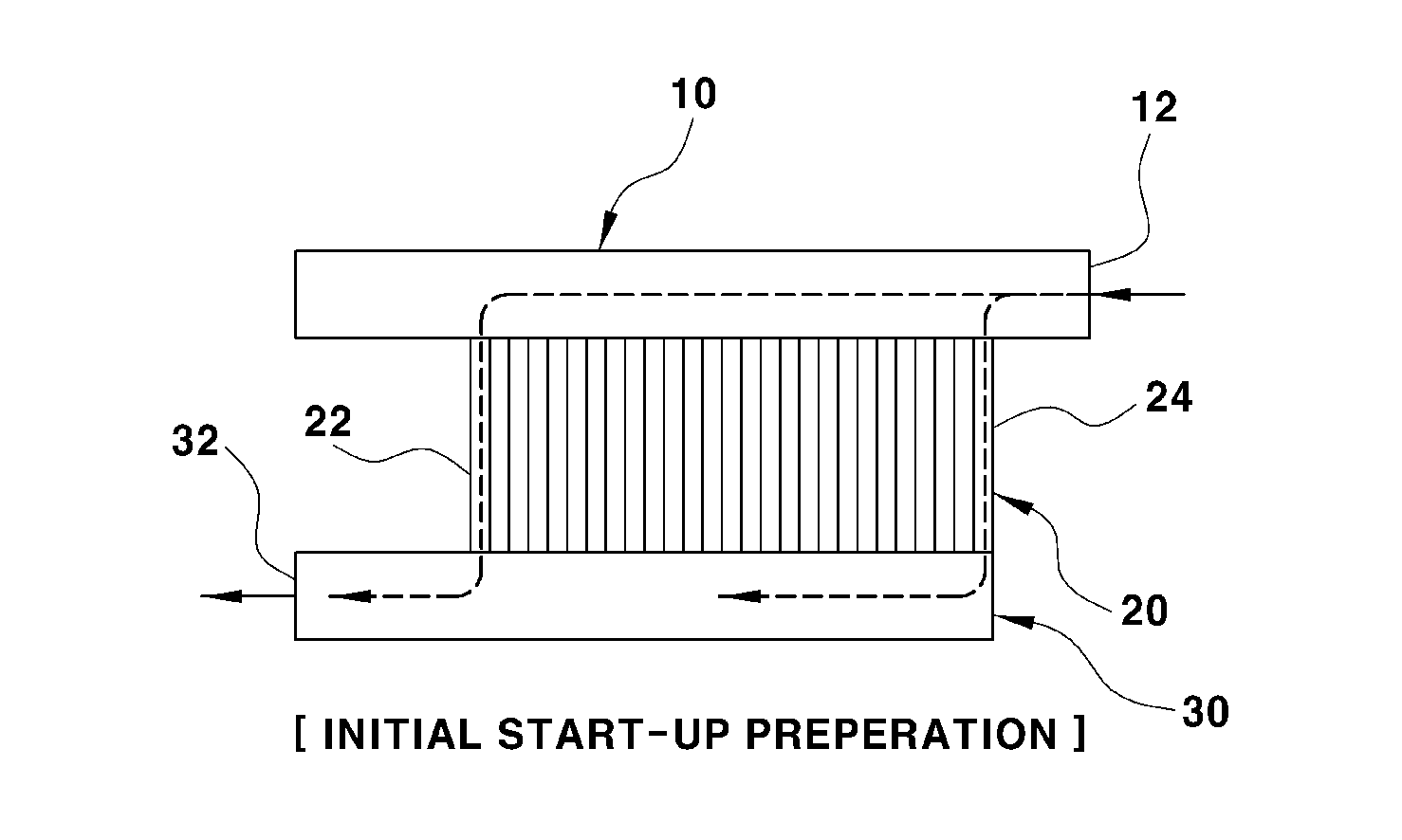
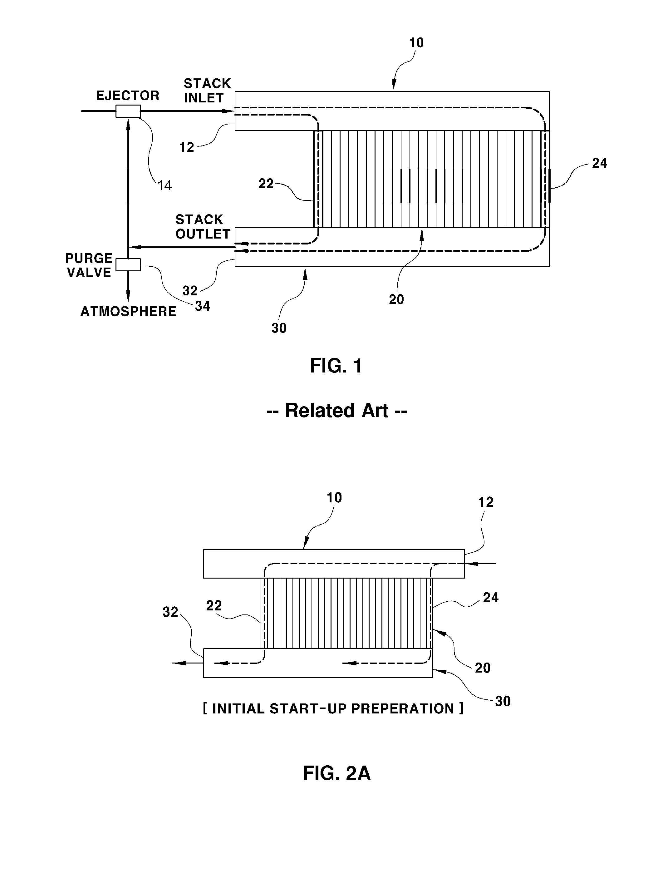
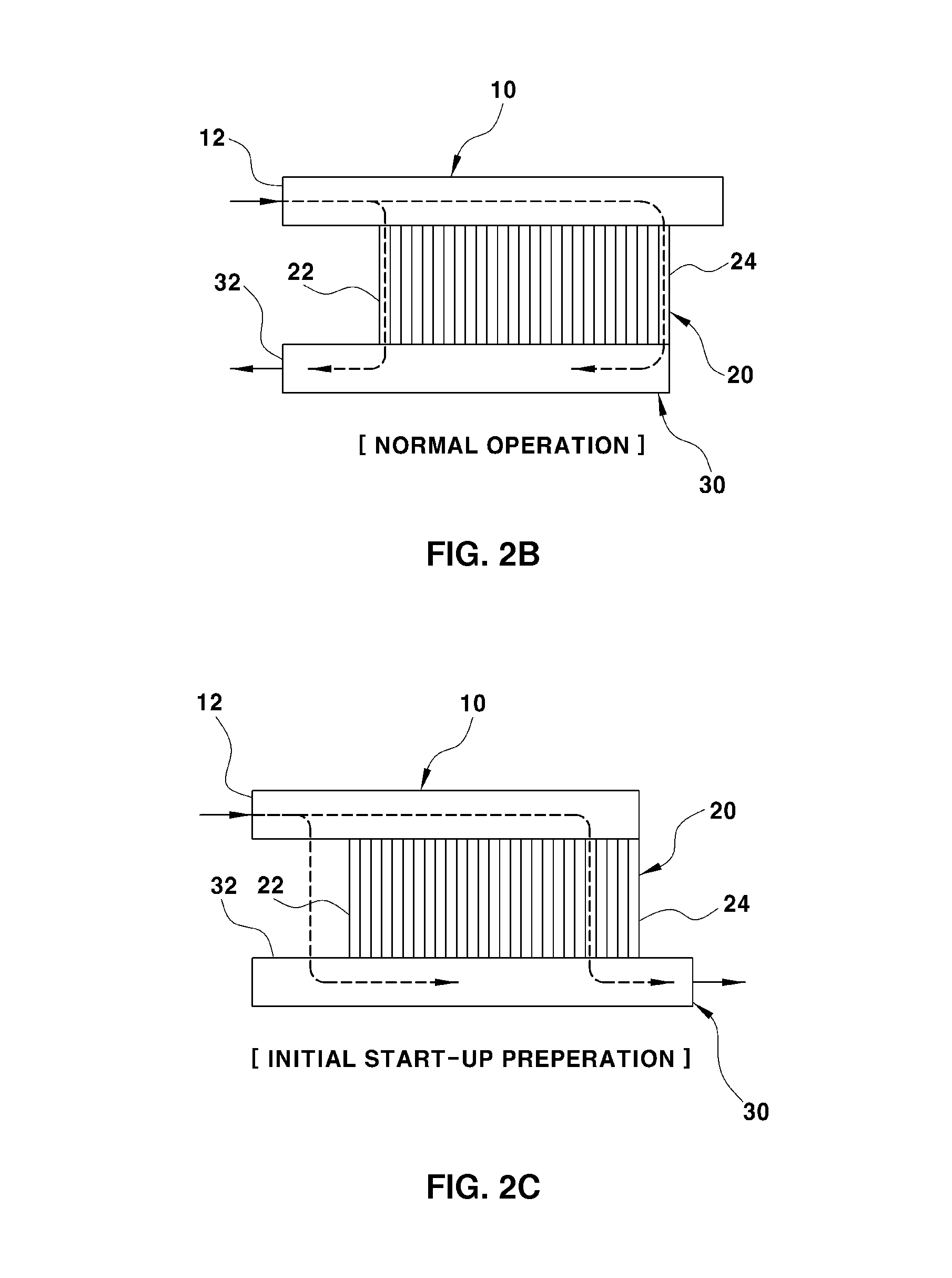
[0042]For the purpose of helping the present disclosure to be understood, the operation concept of a hydrogen purge process during an initial start-up and a normal operation when a device for changing an anode inlet and an anode outlet of the present disclosure is used will be described with reference to FIGS. 2A-2D as follows.

[0043]FIGS. 2A-2D are conceptual diagrams illustrating a hydrogen purge process during a start-up of a fuel cell vehicle and a normal operation when a device for changing an anode inlet and an anode outlet of a fuel cell stack is used according to an embodiment of the pre


PUM


Abstract

A device for changing an anode inlet and an anode outlet of a fuel cell stack includes an inlet manifold connected the anode inlet of the fuel cell stack and an outlet manifold connected to the anode outlet. An inlet and outlet changing means is disposed inside one of the inlet manifold and the outlet manifold and controls flow directions of the anode inlet and the anode outlet to be the same or opposite to each other.

Description


Claims


Application Information

Patent Timeline
Owner HYUNDAI MOTOR CO LTD
Why Eureka
Try Eureka