Cooling system for vehicles and control method thereof

Active Publication Date: 2019-05-09
HYUNDAI MOTOR CO LTD +1
View PDF0 Cites 1 Cited by
  • Summary
  • Abstract
  • Description
  • Claims
  • Application Information

AI Technical Summary

Benefits of technology

The present patent is about a cooling system for vehicles that improves indoor heating performance by controlling the flow rate of coolant passing through a heater core and an EGR cooler. The system includes a control method using a water temperature sensor and a flow rate control valve positioned at the inlet and outlet of the engine. This control method ensures efficient fuel through a high-speed warm-up of the engine by controlling the flow rate of coolant passing through the EGR cooler and the heater core. Additionally, the control method prevents overheating of the EGR cooler by controlling the open control of the heater core port disposed on the EGR cooler when the outlet coolant temperature exceeds a set temperature.

Problems solved by technology

However, since the EGR cooler is restricted to a specific position, the arrangement of the EGR cooler as described above may degrade the ability to control other valves used to control the coolant.

Method used


Image

  • Cooling system for vehicles and control method thereof
  • Cooling system for vehicles and control method thereof
  • Cooling system for vehicles and control method thereof

Examples


Embodiment Construction

[0022]Exemplary embodiments of the present disclosure will be described in detail with reference to the accompanying drawings.

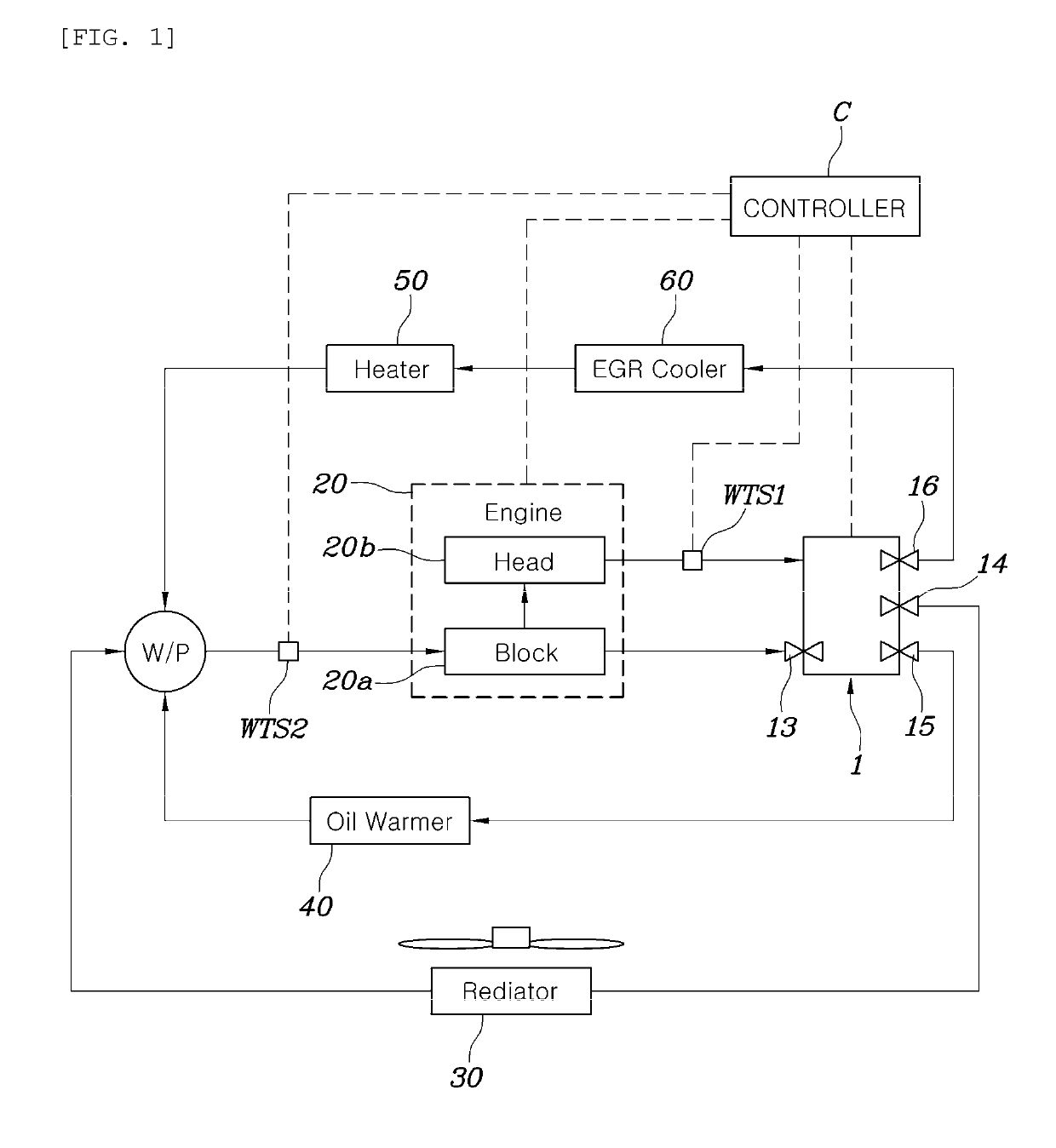
[0023]FIG. 1 is a view illustrating a configuration of a cooling system for vehicles according to the present disclosure. An inlet water temperature sensor WTS2 is installed on a flow path of an inlet side of an engine and an outlet water temperature sensor WTS1 is installed on a flow path of an outlet side of the engine.

[0024]In addition, a flow rate control valve 1 is installed at a rear end of the outlet water temperature sensor WTS1. Such a flow rate control valve 1 may variably control four ports at one time by an operation of only a valve body included in the valve.

[0025]For example, the flow rate control valve 1 is provided with at least three or more discharge ports. The respective discharge ports may be each connected to flow paths on which a radiator 30, an oil heat exchanger such as oil warmer 40, or the like, and a heater core 50 are disposed, the...


PUM


Abstract

A cooling system for vehicles and a control method thereof improves indoor heating performance and fuel efficiency by controlling a flow rate of a coolant passing through a heater core together with an EGR cooler. A coolant having an increased temperature is first supplied to the heater core side through a flow stagnancy control to rapidly increase the temperature of the coolant flowing in the heater core, thereby improving heating performance. A warm-up feature is improved through an exhaust heat recovery function by a heat exchange between the exhaust gas and the coolant in the EGR cooler, thereby improving efficiency of fuel.

Description

CROSS REFERENCE TO RELATED APPLICATION[0001]This application claims the benefit of Korean Patent Application No. 10-2017-0147211 filed on Nov. 7, 2017, entitled “Cooling System for Vehicles and Control Method Thereof”, which is hereby incorporated by reference in its entirety into this application.BACKGROUND OF THE DISCLOSURE1. Technical Field[0002]The present disclosure relates to a cooling system for vehicles capable of improving indoor heating performance and fuel efficiency by controlling a flow rate of coolant passing through a heater core together with an EGR cooler, and a control method thereof.2. Description of the Related Art[0003]A cooling system using a mechanical and wax-type thermostat measures a temperature of coolant using only one water temperature sensor at an outlet side of an engine, and determines and controls a use start temperature of an EGR cooler using the measured temperature of the coolant.[0004]To this end, since the temperature of the coolant at the outle...

Claims


Application Information

Patent Timeline
IPC IPC(8): F01P7/16
CPCF01P7/165F01P2007/146F01P2025/30F01P2025/32F01P3/20F01P2060/08F02M26/28F01P7/16F02D41/0077F01P7/14
Inventor PARK, CHEOL SOOCHAE, DONG SUKLEE, PHIL GIPARK, JUN SIKYI, JEA WOONG
Owner HYUNDAI MOTOR CO LTD
Why Eureka
Try Eureka