Electric discharge machine

Active Publication Date: 2017-02-02
FANUC LTD
View PDF2 Cites 2 Cited by
  • Summary
  • Abstract
  • Description
  • Claims
  • Application Information

AI Technical Summary

Benefits of technology

[0025]According to the present invention, it is possible to provide an electric discharge machine having a func

Problems solved by technology

If the moisture amount is reduced in machining liquid in which water and oil are mixed, this could be a cause to largely reduce machining speed of the electric discharge machining or to hinder stable electric discharge machining.
When a weight of a workpiece is measured in a wire electric discharge machine, it is general to measure the weight using a scale, but when a workpiece having a large weight is to be measured, it is necessary to prepare a large measuring device, and there is a problem that the measuring operation requires labor.
When a workpiece to be electric discharge machined is placed on a table in a machining tank, there is a problem that a machine body of a casting or a guide is distorted under the influence of the weight of the workpiece, and a pitch error is influenced.
However, when workpieces having different weights are continuously machined, since it is necessary to measure the weight in each case, the weight-measuring operation o

Method used


Image

  • Electric discharge machine
  • Electric discharge machine
  • Electric discharge machine

Examples


Embodiment Construction

[0031]An embodiment of the present invention will be described together with the drawings.

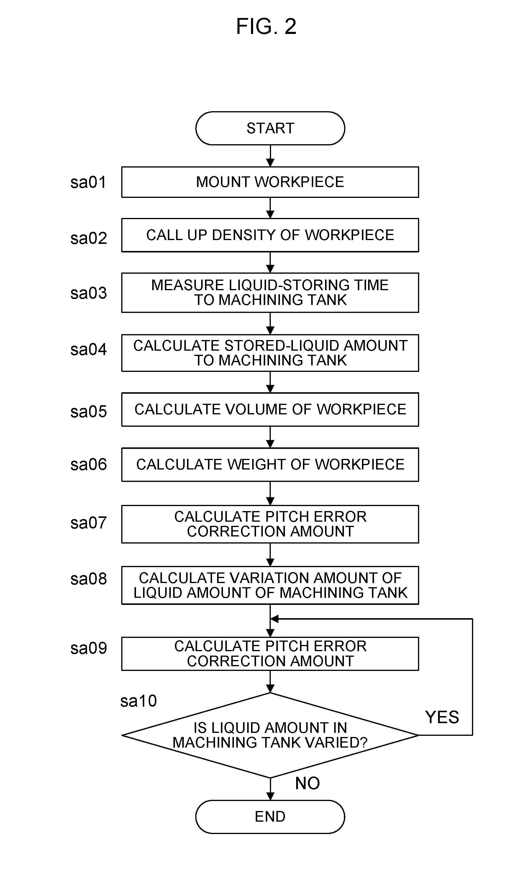
[0032]A wire electric discharge machine having a function to automatically calculate a weight of a workpiece to be machined according to the present invention will be described. More specifically, a weight W1 of a workpiece is automatically calculated by executing the following process.

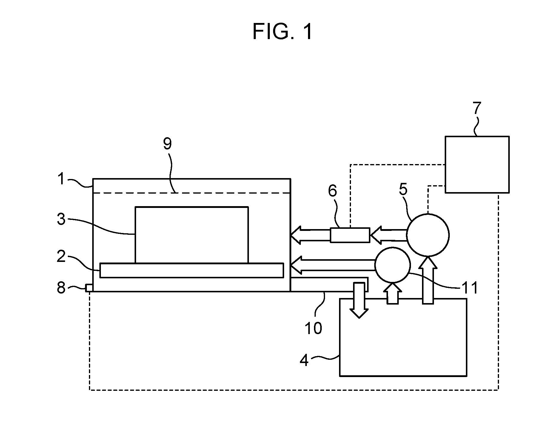
[0033]FIG. 1 is a schematic diagram of the electric discharge machine.

[0034]A liquid level h1 of a machining tank 1 is measured using a liquid level measuring section which measures a liquid level of the machining tank 1 when machining liquid is stored in the machining tank 1 from a liquid storage tank 4. More specifically, a liquid level (machining tank liquid level 9) stored in the machining tank 1 uses data acquired from a liquid level sensor 8 mounted in the machining tank 1. Instead of the liquid level sensor 8, there are also a method in which a height (=position of upper electrode support portion, position of


PUM

PropertyMeasurementUnit
Weightaaaaaaaaaa
Flow rateaaaaaaaaaa
Densityaaaaaaaaaa

Abstract

A machining liquid is supplied to a predetermined level when a workpiece is on a table. A volume of the workpiece is obtained from a difference between the machining liquid amount at the predetermined level when a previous workpiece is not on the table, and the machining liquid amount when the workpiece is on the table. A weight of the workpiece is obtained from the obtained volume and a previously stored density of the workpiece. A weight of a mounting jig is obtained in the same procedure. A total volume of the jig and workpiece is obtained when the jig is on the table and the workpiece is fixed to the jig. The volume of the workpiece is obtained by a difference with respect to the volume of the jig. The weight of the workpiece fixed to the jig is obtained from the obtained volume and the previously stored density.

Description


Claims


Application Information

Patent Timeline
Owner FANUC LTD
Why Eureka
Try Eureka