Heat exchanger for power-electronic components

a technology of heat exchanger and power-electronic components, which is applied in the direction of cooling/ventilation/heating modification, tubular elements, lighting and heating apparatus, etc., can solve the problems of limited cooling performance compared to water cooling, restrict the application of two-phase cooling systems in power-electronic systems, etc., to increase the current rating of power-electronic systems, increase the efficiency of heat exchangers, and increase the effect of losses

Active Publication Date: 2017-07-13
ABB (SCHWEIZ) AG
View PDF0 Cites 6 Cited by
  • Summary
  • Abstract
  • Description
  • Claims
  • Application Information

AI Technical Summary

Benefits of technology

This patented technology allows for integrating multiple phases of a heat exchange unit into one piece of equipment called an Air Cooled Power Electronics System or simply ACESC). By adding this component to existing systems like those mentioned earlier, it becomes possible to increase its ability to dissipate more energy during operation without overheating them down too much. Additionally, by incorporation of these components within certain specifications, they also improve their efficiency even under different conditions such as high temperatures or low currents. Overall, this design improves overall functionality and durability of the ACCESC's while reducing costs associated therewith.

Problems solved by technology

This patented technical problem addressed in this patents relates to improving the efficiency of electronic systems' cooling during high power operations while minimizing costs associated therewith. Two phase coolant systems have been developed for PE systems but they still suffer from issues like poor coolability when operating below certain limits. Passively two-phased coolants offer better cooling capabilities without requiring expensive equipment and maintain their effectiveness even after long periods of time under harsh environmental conditions.

Method used


Image

  • Heat exchanger for power-electronic components
  • Heat exchanger for power-electronic components
  • Heat exchanger for power-electronic components

Examples


Embodiment Construction

[0026]In the following, various aspects and embodiments of the invention are described. It is intended that each of the aspects, whether described in the context of a particular embodiment or of other features or not, can be combined with any other aspect.

[0027]In the figures and the following description, the same reference numbers are used for analogous elements, and the description of any embodiment relating to the same reference sign is applicable to any other embodiment unless mentioned otherwise and / or unless the description would be inconsistent with that embodiment.

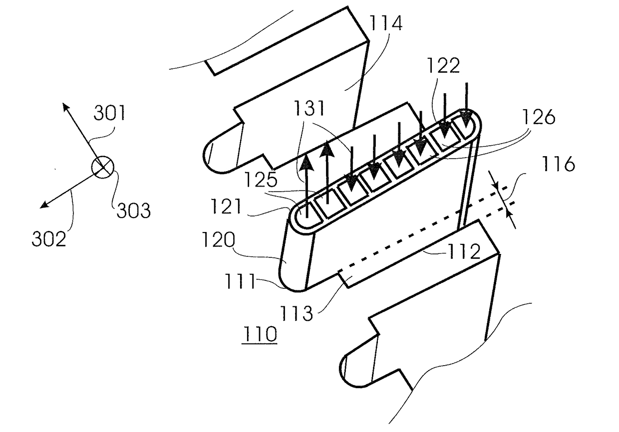
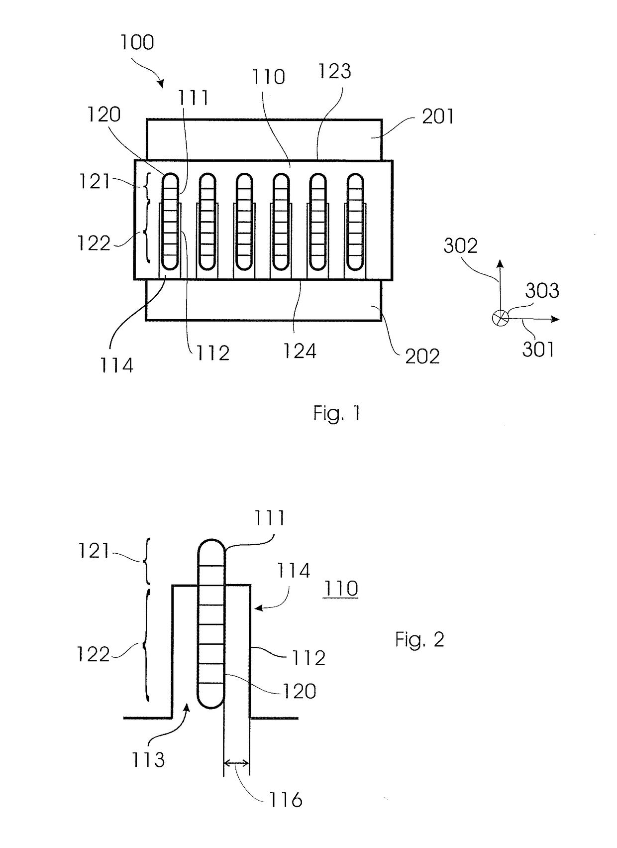
[0028]FIG. 1 shows a two-phase heat exchanger device 100 according to embodiments described herein. The heat exchanger device 100 is exemplarily shown in FIG. 1 as being stacked between two semiconductor modules 201 and 202. Typically, the heat exchanger device 100 and the two semiconductor modules 201, 202 are stacked in a stacking direction 302 as can be seen in the coordinate system in FIG. 1. According to some


PUM


Abstract

It is proposed a two-phase heat exchanger device for a power-electronic module arrangement having a semiconductor module. The two-phase heat exchanger device includes a base plate configured for being in contact with a first semiconductor module at a first side of the base plate; and at least one tube element for a first cooling medium including a first portion having at least one evaporator channel and a second portion having at least one condenser channel. The base plate has a groove containing the tube element, wherein the groove is dimensioned for enabling thermal contact between the base plate and the first portion of the tube element and dimensioned to form a gap between the base plate and the second portion of the tube element for thermal separation of the base plate and the second portion of the tube element.

Description


Claims


Application Information

Patent Timeline
Owner ABB (SCHWEIZ) AG
Why Eureka
Try Eureka