Damper for a covering for an architectural opening

Active Publication Date: 2018-01-04
HUNTER DOUGLAS INC
View PDF2 Cites 2 Cited by
  • Summary
  • Abstract
  • Description
  • Claims
  • Application Information

AI Technical Summary

Benefits of technology

[0003]The present disclosure generally provides a damper that offers improvements and/or an alternative to existing dampers for an architectural covering. The damper generally provides multiple or varying levels of damping between defined end points of travel. In some arrangements, the damper provides increased damping adjacent the end points of travel and decreased damping therebetween. When as

Problems solved by technology

However, the one or more shade members do not always move in such a desired manner.
Moving the louvers into a closed position sometimes create

Method used


Image

  • Damper for a covering for an architectural opening
  • Damper for a covering for an architectural opening
  • Damper for a covering for an architectural opening

Examples


Embodiment Construction

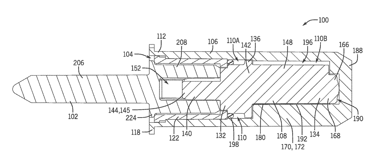
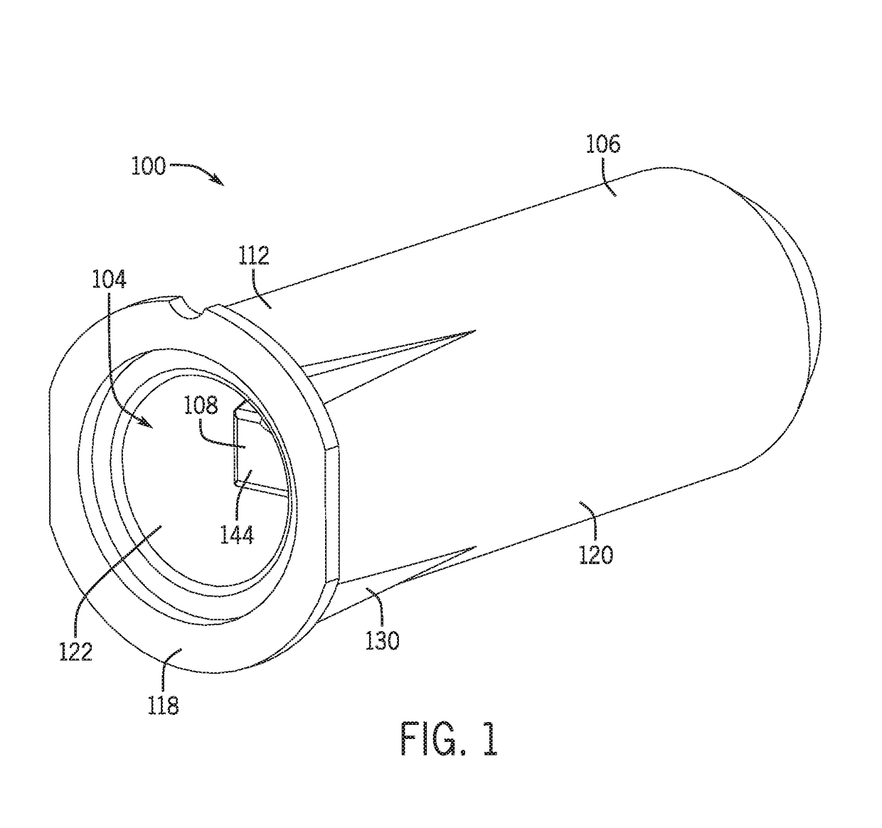
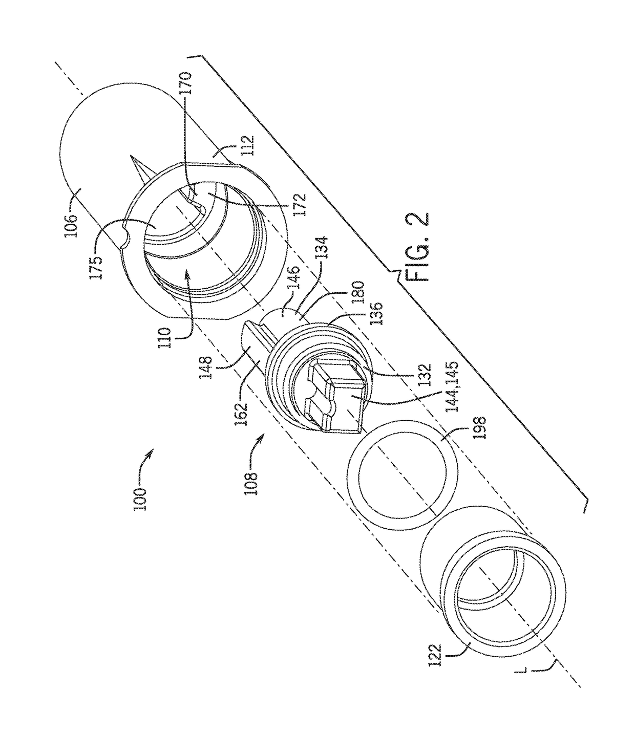
[0025]FIG. 1 illustrates a damper 100 according to an illustrative embodiment of the present disclosure. The damper 100 of the illustrative embodiment is configured to interface with an external component 102 or drive member (e.g. a louver pin) (see FIG. 3) that transfers rotation to the damper 100, and to which the damper 100 imparts a resistive force to control a rate of movement of the external component 102 (see FIG. 3). The damper 100 may resist rotational movement of the external component 102 about a longitudinal axis L of the damper 100 (see FIG. 2). The damper 100 may include an opening 104 defined in an end of the damper 100 configured to receive a portion of the external component 102 (see FIG. 4).

[0026]With reference to FIGS. 2 and 4-11, the damper 100 of the illustrative embodiment includes a housing 106 and a rotary member 108 rotatably received at least partially in the housing 106. Referring to FIGS. 4-11, the housing 106 may be substantially hollow and may define an in


PUM


Abstract

A damper providing varying damping force is provided. The damper may include a housing and a rotary member rotatably received the housing. The rotary member may rotate within the housing between defined end points of travel to define an angular range of travel of the rotary member. An outermost surface of the rotary member may be spaced inwardly from an inner surface of the housing defined between the end points of travel to define a gap between the outermost surface of the rotary member and the inner surface of the housing throughout the angular range of travel. The gap may vary in dimension depending on a rotational position of the rotary member to provide varying damping rates within the angular range of travel of the rotary member.

Description


Claims


Application Information

Patent Timeline
Owner HUNTER DOUGLAS INC
Why Eureka
Try Eureka