Spreader plate load distribution

a technology of spreader plate and load distribution, which is applied in the direction of seat heating/ventilation devices, vehicle components, vehicle arrangements, etc., can solve the problems of fuel efficiency loss and interior space loss of vehicles, and achieve the effect of limited flexure of the spreader pla

Active Publication Date: 2018-03-01
FORD GLOBAL TECH LLC
View PDF0 Cites 0 Cited by
  • Summary
  • Abstract
  • Description
  • Claims
  • Application Information

AI Technical Summary

Benefits of technology

This patent describes an improved design for a seating assembly used in vehicles. It involves adding a seat back and an inflated bladders inside it. There are also a cushion assembly placed above them. These components help reduce pressure from sitting down while still providing comfort during long journeys or when riding up outdoors.

Problems solved by technology

The technical problem addressed by this patent is how to design a more flexible and lightweight seatback for vehicles without compromising its ability to withstand high levels of impact from collisions or accelerations during use.

Method used


Image

  • Spreader plate load distribution
  • Spreader plate load distribution
  • Spreader plate load distribution

Examples


Embodiment Construction

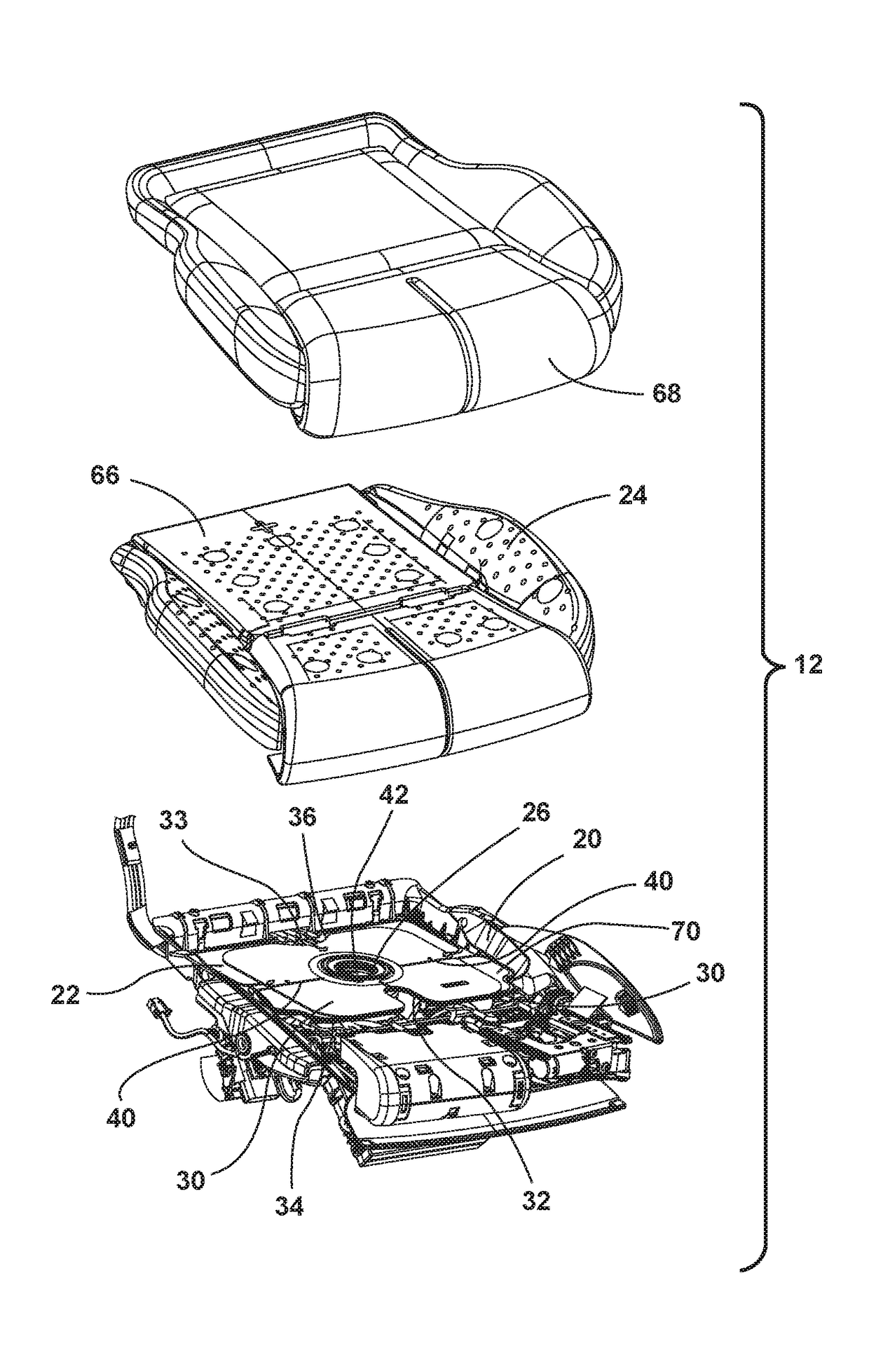
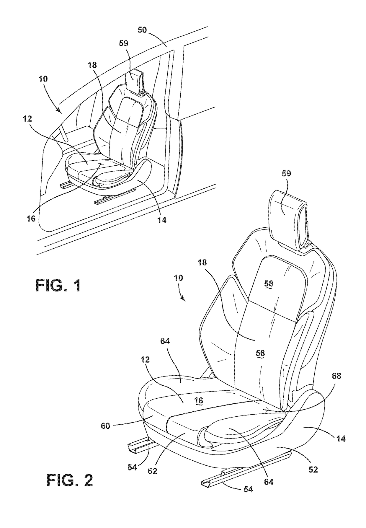
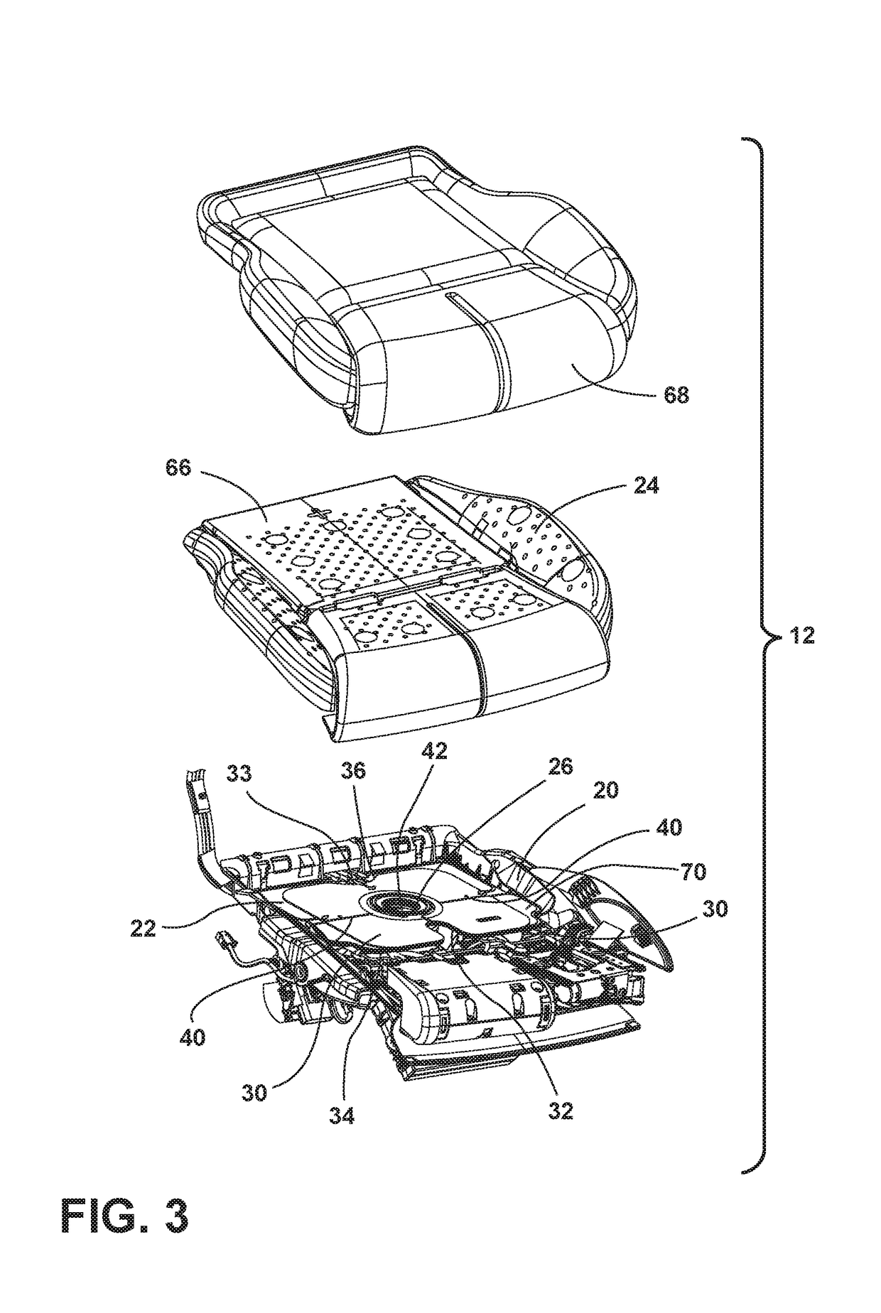
[0015]For purposes of description herein, the terms “upper,”“lower,”“right,”“left,”“rear,”“front,”“vertical,”“horizontal,” and derivatives thereof shall relate to the disclosure as oriented in FIG. 1. However, it is to be understood that the disclosure may assume various alternative orientations, except where expressly specified to the contrary. It is also to be understood that the specific devices and processes illustrated in the attached drawings, and described in the following specification are simply exemplary embodiments of the inventive concepts defined in the appended claims. Hence, specific dimensions and other physical characteristics relating to the embodiments disclosed herein are not to be considered as limiting, unless the claims expressly state otherwise.

[0016]In this document, relational terms, such as first and second, top and bottom, and the like, are used solely to distinguish one entity or action from another entity or action, without necessarily requiring or implyin


PUM


Abstract

A seating assembly includes a seat having a seat frame. The seat generally defines a seating surface. A seatback is pivotally coupled with the seat. A carrier is disposed on the seat frame and supports a multi-contour seating component that is adjustable to change a contour of the seating surface. A cushion assembly is disposed over the multi-contour seating component of the seat and is in communication with a climate control system. A spreader plate is disposed below the cushion assembly. The spreader plate is configured to balance load distribution across the seating surface when the multi-contour seating component is activated. The spreader plate includes flex recesses defined in forward and rearward walls of the spreader plate. Lateral flex breaks allow limited flexure of the spreader plate. An inner opening is in communication with the climate control system.

Description


Claims


Application Information

Patent Timeline
Owner FORD GLOBAL TECH LLC
Why Eureka
Try Eureka