In-vehicle network system

Active Publication Date: 2018-05-10
TOYOTA JIDOSHA KK
View PDF8 Cites 8 Cited by
  • Summary
  • Abstract
  • Description
  • Claims
  • Application Information

AI Technical Summary

Benefits of technology

[0051]According to the aspect of the disclosure, it is possible to provide an in-vehicle network system in which both of securing a security level and suppressing a decrease in commu

Problems solved by technology

Incidentally, in a case where the external device is connected to a network built by the bus as described above, the driving support device of the related art does not increase a security level of data communication in the network.
With the development of information technology, there are various types of external devices, and therefore, the number of external devices in which a problem may be caused is increasing.
Further, the external device in which a problem may be caused is, for example, a non-genuine device that is not approved by the manufacturer of the vehicle.
Thus, when the security level does not increase in a case where the external device in which a problem may be caused is connected to the bus, an in-vehicle network or a control device or the like connected to the network is likely to

Method used


Image

  • In-vehicle network system
  • In-vehicle network system
  • In-vehicle network system

Examples


first embodiment

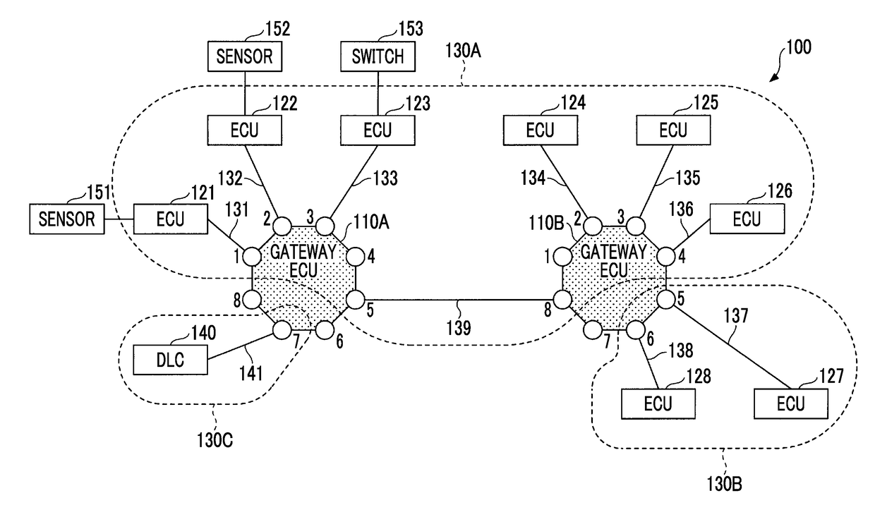
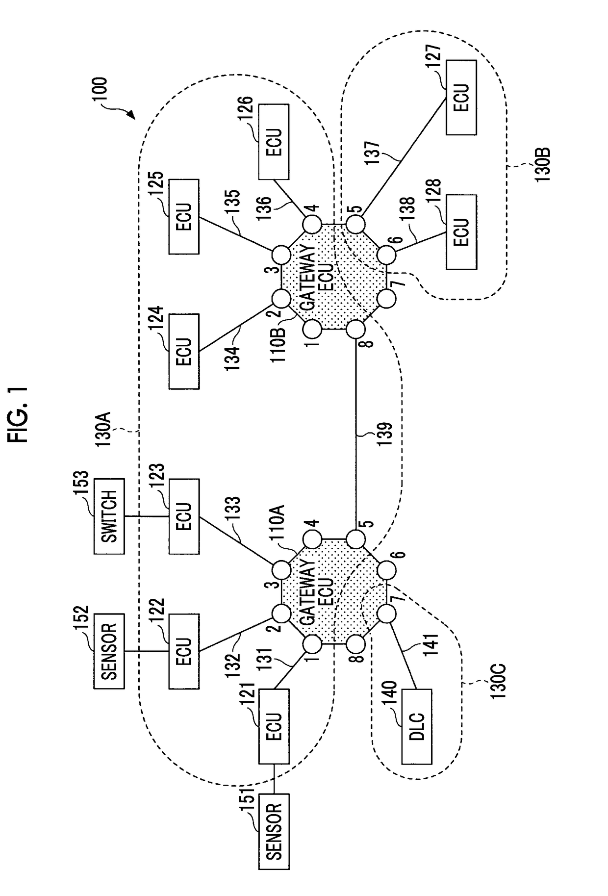
[0067]FIG. 1 is a diagram illustrating an in-vehicle network system 100 according to a first embodiment. The in-vehicle network system 100 is mounted on a vehicle.

[0068]The in-vehicle network system 100 includes relay devices (hereinafter referred to as gateway electronic control units (ECUs)) 110A, 110B, a plurality of controllers (hereinafter referred to as ECUs) 121, 122, 123, 124, 125, 126, 127, 128, communication lines 131, 132, 133, 134, 135, 136, 137, 138, 139, 141, and a data link connector (DLC) 140. Sensors 151, 152 are connected to the ECUs 121, 122, respectively, and a switch 153 is connected to the ECU 123.

[0069]The in-vehicle network system 100 uses, for example, an Ethernet protocol as a communication protocol. The communication lines 131, 132, 133, 134, 135, 136, 137, 138, 139, 141 do not indicate physical buses, and are virtual communication lines that build virtual local area networks (VLANs) 130A, 130B, 130C according to the Ethernet protocol.

[0070]The VLAN 130A is b

second embodiment

[0175]FIG. 11 is a diagram illustrating a relationship between a path for data to be transferred and an L2 switch, an L3 switch, and an L7 switch in an in-vehicle network system 200 according to a second embodiment.

[0176]The in-vehicle network system 200 according to the second embodiment has a configuration obtained by adding an ECU 129, a communication line 231, and a data communication module (DCM) 600 to the in-vehicle network system 100 according to the first embodiment.

[0177]The ECU 129 is connected to a port 7 of a gateway ECU 110B via the communication line 231. In the second embodiment, the ECU 129 is used as an example of a connector capable of connecting the DCM 600.

[0178]The VLAN 130D is built by the communication line 231, and the gateway ECU 110B and ECU 129 are connected thereto. The communication line 231 is an example of a second communication line. In FIG. 11, anything is not connected to the DLC 140.

[0179]Since a configuration other than the above-described configura


PUM


Abstract

An in-vehicle network system includes a plurality of first controllers; a plurality of first communication lines, the first communication lines being respectively connected to the first controllers; a connector that connects an external device or a wireless communication device; a connection communication line that is connected to the connector; and a first relay device that relays between the first communication lines and the connection communication line. The first relay device is configured to determine whether a security level in data communication between the first controllers is increased according to a type of the external device or a communication state of the wireless communication device in a state in which the external device or the wireless communication device is connected to the connector, and the first relay device is configured to increase the security level when the first relay device determines that the security level is increased.

Description


Claims


Application Information

Patent Timeline
Owner TOYOTA JIDOSHA KK
Why Eureka
Try Eureka