Luggage cases

a luggage case and luggage technology, applied in the field of luggage cases, can solve the problems of cumbersome and costly approach, limited luggage case size, and inability to carry the same luggage case on the plane,

Active Publication Date: 2018-06-28
24 7 INT
View PDF10 Cites 4 Cited by
  • Summary
  • Abstract
  • Description
  • Claims
  • Application Information

AI Technical Summary

Benefits of technology

This patent describes a new type of bag with two parts: one has a storage area and another has a separate part called a stretchable handle. When it's collapsed, there are spaces inside where other things can be stored. It also includes an extension handle that allows users to pull on them easily. An elastomeric handle connects to both the handles and helps fit into different ways.

Problems solved by technology

The technical problem addressed in this patent is how to provide two types of carrying cases: large and small ones, which are suitable for different purposes depending on their intended use.

Method used


Image

  • Luggage cases
  • Luggage cases
  • Luggage cases

Examples


Embodiment Construction

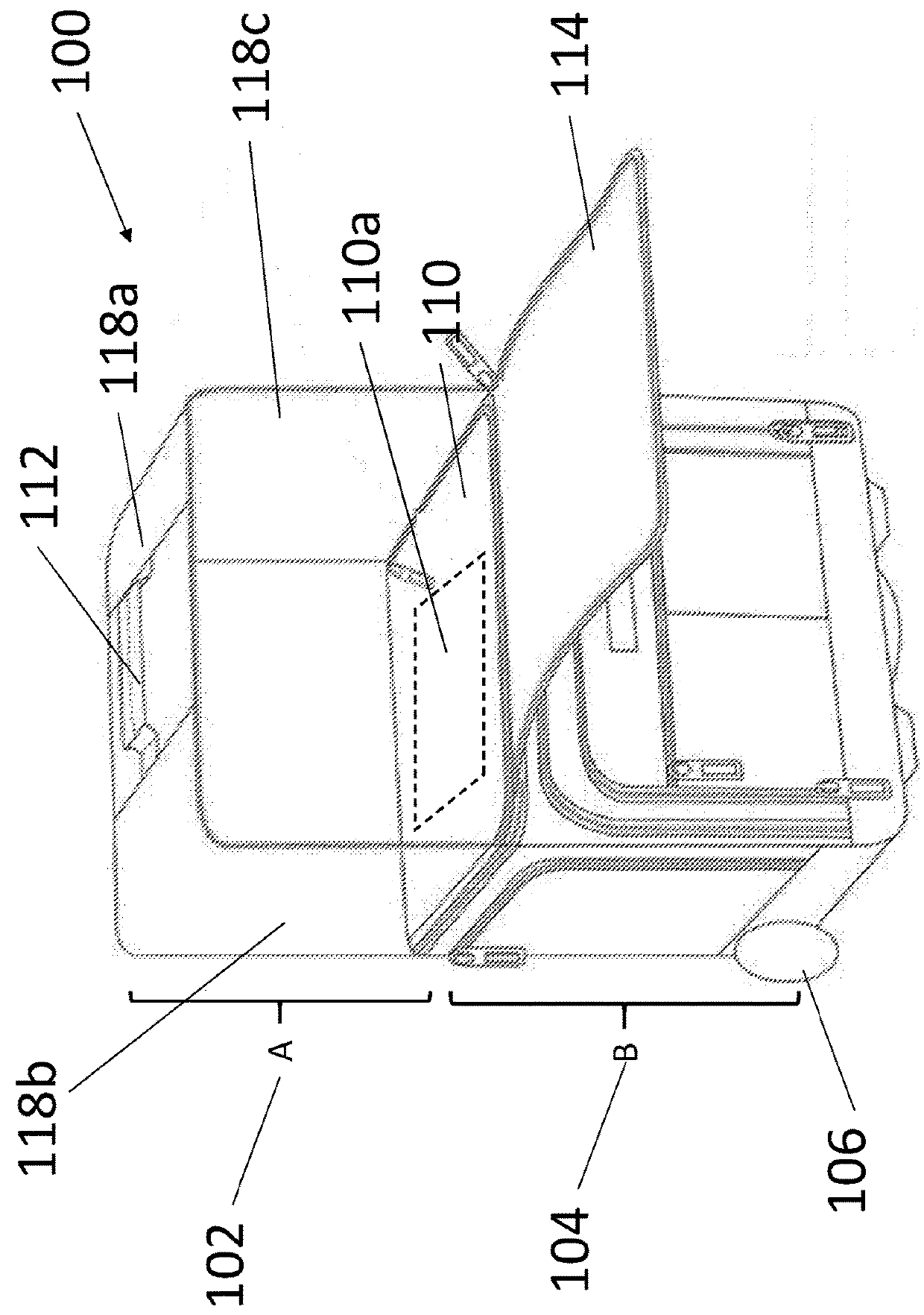
[0011]As indicated above, the subject matter presented herein provides for a luggage case that is capable of transforming between a under the seat type luggage case and a regular carrier on luggage case.

[0012]FIG. 1 illustrates an exemplary embodiment of a luggage case 100 in accordance with the subject matter disclosed herein. This luggage case 100 may include a second portion A 102 that is collapsible or capable of being folded, and a first portion B 104 that's designed to function in a substantially rigid (i.e., not foldable) fashion. Normally, the first portion B 104 can have the size of an average luggage case that may be placed underneath a passenger's seat on a commercial airplane and designed to have the storage space that is comparable to an average under the seat luggage case. The first portion B 104 may assume a rectangular boxy shape in general (e.g., cubical in shape) or other geometric shapes commonly adopted in the industry, and portion B 104 may further have a pair of w


PUM


Abstract

Provided herein is a luggage case having a first portion having a storage space, a second foldable portion having at least one expandable sleeve for transforming between a folded configuration and an expanded configuration, a separation member positioned between the first portion and the second foldable portion, the separation member separating the first and second portions such that when the second foldable portion is in the folded configuration the separation member prevents the second foldable portion from take away any storage space from the first portion. The luggage case may further have an extendable handle bar having at least one extendable bar, the extendable handle bar being connected to the first portion for pulling the luggage case, and an elastic handle connected to the second foldable portion and configured to accommodate the extendable handle bar such that when the second foldable portion is in the expanded configuration the elastic handle presses the extendable handle against the second foldable portion.

Description


Claims


Application Information

Patent Timeline
Owner 24 7 INT
Why Eureka
Try Eureka