Finishing device

Active Publication Date: 2018-11-22
URBAN MACHINERY CORP
View PDF11 Cites 4 Cited by
  • Summary
  • Abstract
  • Description
  • Claims
  • Application Information

AI Technical Summary

Benefits of technology

[0029]Moreover, at least one tool is located in the middle area between the ends of the tool holder, in particular on the side, or back side, opposite the interface. This proposal allows a larger number of tools to be disposed on the tool holder, and clever guidance of the tool holder allows problem-free use of the tools. For example, in the middle area not just one, but a plurality of tools can be provided next to one another, if necessary oriented differently. Of course, due to the larger number of tools, the flexibility of such an arrangement also increases.
[0030]In particular, it is advantageous to be able to dispose a tool on the back side precisely opposite the interface more mechanically durable in the direction of the tool axis (the rotational axis of the tool) since these forces can be introduced directly to the last arm element of the machining arm and as such not apply any damaging torque to the last arm element. This can be a drill, for example.

Problems solved by technology

In the process, the plastic profile is first mitered, the mitered surfaces are heated by the welding plate of a welder and the hot mitered surfaces are pressed, and thus welded, together, resulting in a solid mechanical connection A weld bead results, consisting of plastic material that is heated and displaced from the contours of the two profiles during the joining process; this material must be removed after welding since for one thing this weld bead is unattractive to look at, and for another it can be functionally disruptive on the inside.
The disadvantage to this design is that the support arm must be stable since the blade is responsible for removing the weld bead and bead chips, and the working force to accomplish this must come from the motion of the support arm.
To work on the inner corners, the tool, which is held by the support arm, must reach into the inner area of the frame and in this case a support arm which is too large, since it was designed to be sturdy, results in corresponding limitations to a minimum window or frame size that can be processed using such a finishing machine.

Method used


Image

  • Finishing device
  • Finishing device
  • Finishing device

Examples


Example

[0037]In the figures, the same elements, or elements that correspond with one another, are identified with the same reference numbers and are therefore not described again unless it is useful to do so. The disclosures contained in the overall description are logically analogous and convertible to the same parts that have the same reference numbers or the same component names. Also, the positional information selected in the description, such as top, bottom, side, etc., refer to the figure directly described and shown and are logically convertible to the new position when a positional change is made. Furthermore, individual features or featural combinations from the various exemplary embodiments shown and described can represent independent, inventive solutions in their own right or according to this invention.

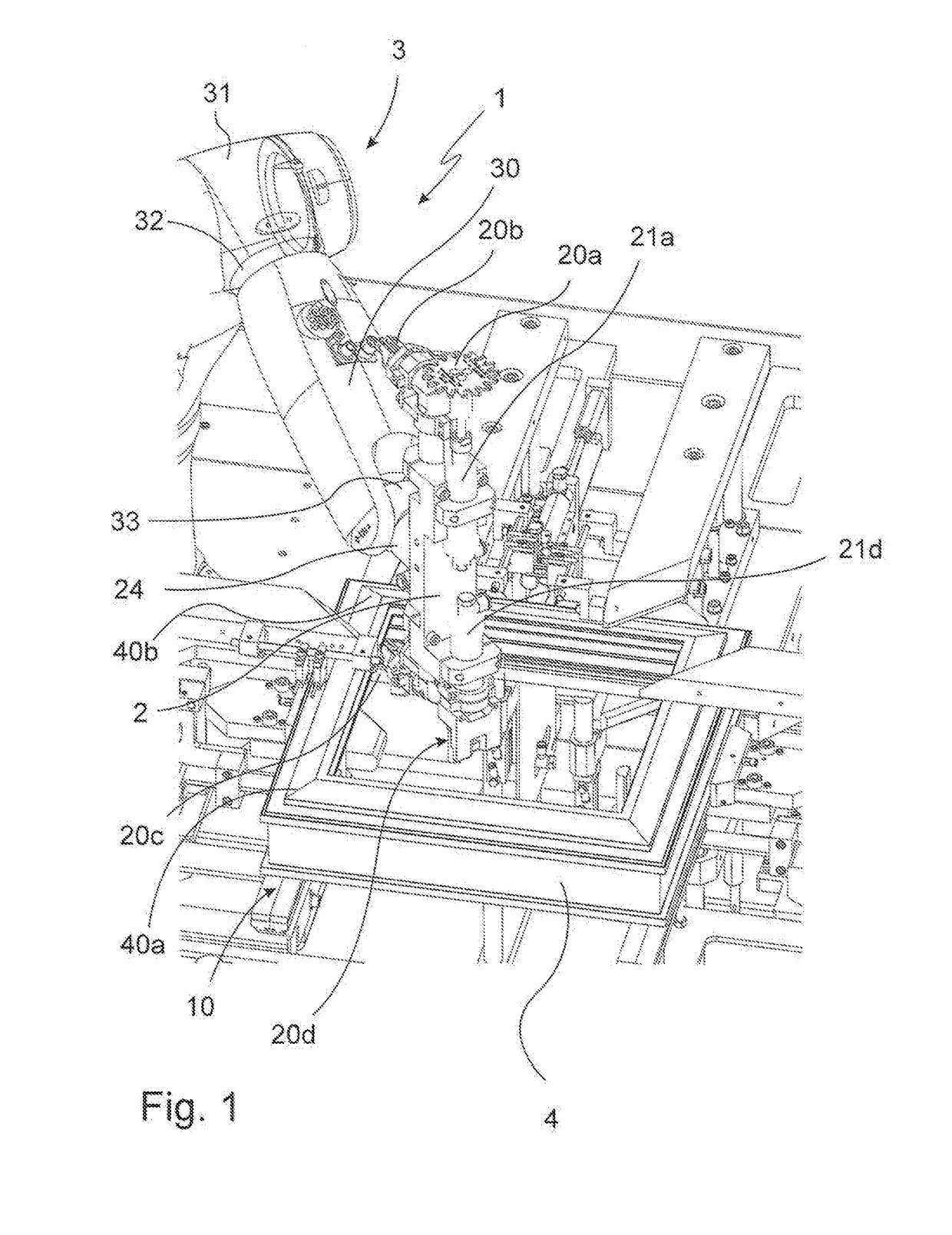
[0038]In FIG. 1, the finishing device 1 according to the invention is shown schematically. The frame to be machined 4, which is a window frame here, lies on a support surface 10 o


PUM

PropertyMeasurementUnit
Angleaaaaaaaaaa

Abstract

The invention relates to a finishing device for removing the weld bead generated during welding of a window or door frame or frame section at the mitered surfaces, wherein the finishing device comprises a support surface for the frame or frame section and a processing arm for supporting a tool holder, and the processing arm consists of a plurality of arm elements that move in hinged fashion relative to one another but can also be fixed in place, wherein the tool holder comprises at least two cutting tools driven by a rotational drive, said tools rotating about a tool axis and at least one tool laterally next to the blade of the tool, contact sides.

Description


Claims


Application Information

Patent Timeline
Owner URBAN MACHINERY CORP
Why Eureka
Try Eureka