Expandable baton structure with hidden smasher at rear end of handle and hidden smasher thereof
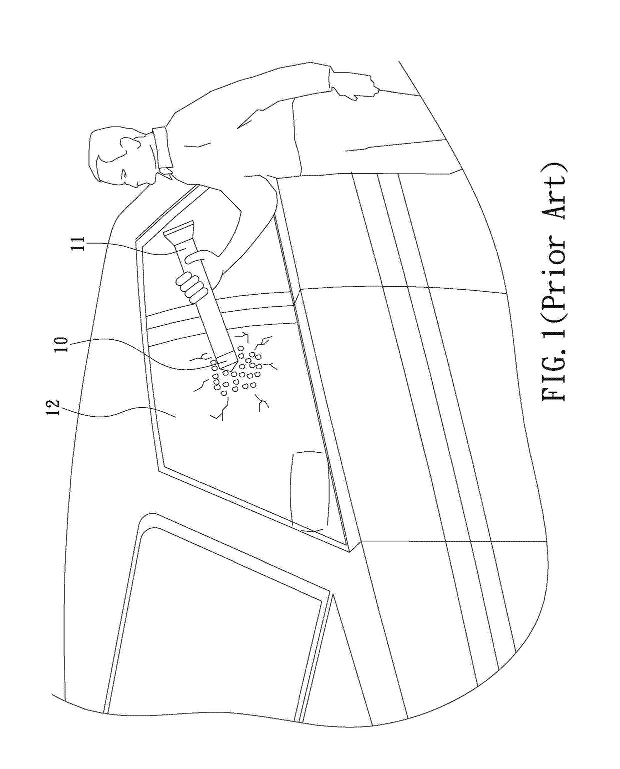
a baton and rear end technology, applied in the field of batons, can solve the problems of preventing escape from a house, car, glass-enclosed environment, tempered glass cannot be quickly smashed without a proper tool, and team members striking it with a hammer, bats or other heavy objects may be injured
- Summary
- Abstract
- Description
- Claims
- Application Information
AI Technical Summary
Benefits of technology
Problems solved by technology
Method used
Image

Examples
first embodiment
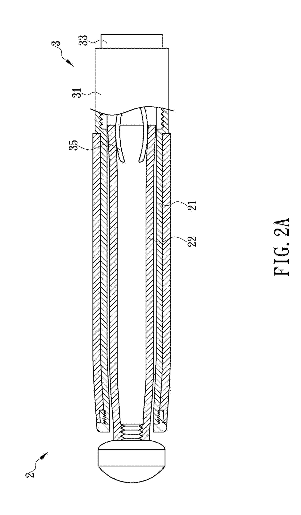
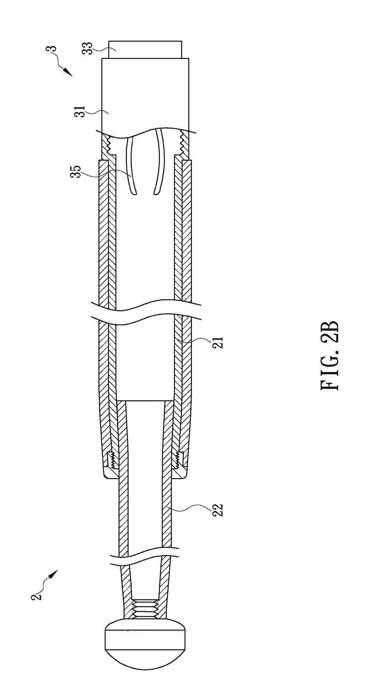
[0016]The present invention is directed to an expandable baton structure with a hidden smasher at the rear end of its handle and also to the hidden smasher itself. In the first embodiment, referring to FIGS. 2A and 2B, the expandable baton structure 2 includes an outer tube 21, at least one inner tube 22, and a hidden smasher 3. The outer tube 21 is telescopically connected with the inner tube 22 and has a rear section forming a handle to be gripped by a user. The outer diameter of the front end of the inner tube 22 is smaller than the inner diameter of the rear end of the outer tube 21 so that the tubes 21 and 22 can be assembled together by inserting the front end of the inner tube 22 into the outer tube 21 through the rear end of the outer tube 21. In addition, the configuration of the rear end of the inner tube 22 matches the configuration of a portion of the outer tube 21 that is adjacent to the front end of the outer tube 21. Therefore, when the expandable baton structure 2 is in
second embodiment
[0024]In the second embodiment, referring again to FIGS. 4A and 4B, an additional compression spring 425 may be mounted around the smashing rod 421 to increase the impact of the smashing rod 421, wherein the additional compression spring 425 has its rear end secured at the smashing rod 421 and its front end pressed against the inner wall of the base 41. When the smashing rod 421 is displaced rearward (i.e., toward the impacting member 422), it drives the impacting member 422 and compresses the additional compression spring 425 simultaneously. When the impacting member 422 subsequently pushes the smashing rod 421 forward (i.e., toward the to-be-smashed object), the additional compression spring 425 releases the elastic energy it stores, thus pushing the smashing rod 421 in conjunction with the compression spring 423 to increase the impact made by the smashing rod 421. Besides, the additional compression spring 425 helps keep the position of the smashing rod 421 to ensure that the smashi
third embodiment
[0028]With continued reference to FIG. 5, when the rear end of the protective cover 53 is pressed against an object to be smashed (e.g., a glass window of a car) and then displaced toward the front end of the hidden smasher 5, the smashing cone 5211 is directly pushed by the to-be-smashed object through the through hole 531. As a result, the smashing rod 521 (i.e., the first rod 521A together with the second rod 521B pushed by the first rod 521A) and the impacting member 522 are displaced in the base 51 toward the front end of the base 51 for a predetermined distance, and the compression spring 523 is substantially compressed by the impacting member 522 and stores a large amount of elastic energy. During the process, the smashing rod 521 (i.e., the second rod 521B) is aligned by the aligning portion 513 such that the axis of the front end of the smashing rod 521 (i.e., the axis of the front end of the second rod 521B) is gradually displaced to a position corresponding to the axis of th
PUM
 Abstract
Description
Claims
Application Information
 - R&D Engineer
- R&D Manager
- IP Professional
- Industry Leading Data Capabilities
- Powerful AI technology
- Patent DNA Extraction
Browse by: Latest US Patents, China's latest patents, Technical Efficacy Thesaurus, Application Domain, Technology Topic.
© 2024 PatSnap. All rights reserved.Legal|Privacy policy|Modern Slavery Act Transparency Statement|Sitemap