Systems and methods for sensing parameters on movers in linear motor systems

a linear motor and parameter sensing technology, applied in the field of linear motor systems, can solve the problems of little or no ability to sense parameters of movers or payloads, little or no other information currently available, and little or no other information

Inactive Publication Date: 2019-02-28
ROCKWELL AUTOMATION TECH
View PDF22 Cites 5 Cited by
  • Summary
  • Abstract
  • Description
  • Claims
  • Application Information

AI Technical Summary

Benefits of technology

The present invention relates to a system for controlling movement within a linear motion machine (LM) track. It includes a linear motor track made up of multiple coil elements and a magnetic component that moves the mover along it. An inductor is used to generate an electromagnetic force between the two components. This causes the mover to move itself around the LM track. There are sensors located at different locations throughout the track to monitor its parameters such as position, velocity, acceleration, etc., which can then transmit this information wirelessly to a receiving device.

Problems solved by technology

This patent describes a problem with current linear motors systems where only limited information can be obtained about the position and movement of each mover within its own frame. Existing solutions have limitations due to lack of knowledge of the movers' movements and payloads' positions themselves.

Method used


Image

  • Systems and methods for sensing parameters on movers in linear motor systems
  • Systems and methods for sensing parameters on movers in linear motor systems
  • Systems and methods for sensing parameters on movers in linear motor systems

Examples


Embodiment Construction

[0027]While only certain features of the invention have been illustrated and described herein, many modifications and changes will occur to those skilled in the art. It is, therefore, to be understood that the appended claims are intended to cover all such modifications and changes as fall within the true spirit of the invention.

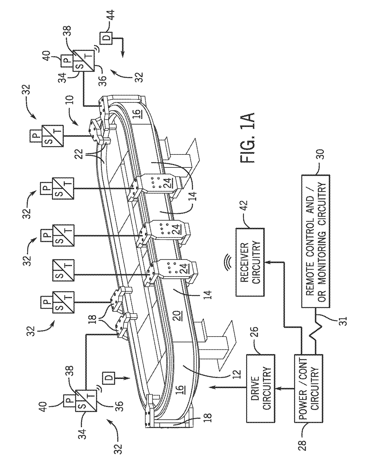
[0028]Turning now to the drawings, and referring first to FIG. 1A, a transport system 10 as illustrated for moving articles or products around a track 12. As will be appreciated by those skilled in the art, in many applications, the transport system will be configured to inter-operate with other machines, robots, conveyers, control equipment, and so forth (not separately shown) in an overall automation, packaging, material handling or other application. The transport system itself generally comprises a “linear motor” system as discussed below, in which the moving components are positioned, accelerated, decelerated, and generally moved under the influence of con


PUM


Abstract

The subject matter of the disclosed invention relates to systems a methods for applying a sensor to linear motor systems. In various embodiments, the disclosed method relates to providing closed loop control on a mover with or without a payload by detecting parameters of the mover, payload, or both.

Description


Claims


Application Information

Patent Timeline
Owner ROCKWELL AUTOMATION TECH
Why Eureka
Try Eureka