Production method for stator

Inactive Publication Date: 2019-06-13
TOYOTA JIDOSHA KK
View PDF0 Cites 0 Cited by
  • Summary
  • Abstract
  • Description
  • Claims
  • Application Information

AI Technical Summary

Benefits of technology

[0016]According to the present disclosure, a production method for a stator core in which a breakage of the stator core can be prevented when a coil is mounted thereon.

Problems solved by technology

In order to improve the performance of a rotary electric machine, there is a problem of how to reduce a loss occurring inside the machine.
In a stator, a core loss (or a high frequency core loss) caused by an eddy current loss or a hysteresis loss occurs, and the motor efficiency and the torque performance are degraded according to these losses.
However, while annealing to facilitate crystallization of the soft magnetic material can result in improvement of the saturation magnetization, the facilitation of crystallization deteriorates the strength of the stator core.
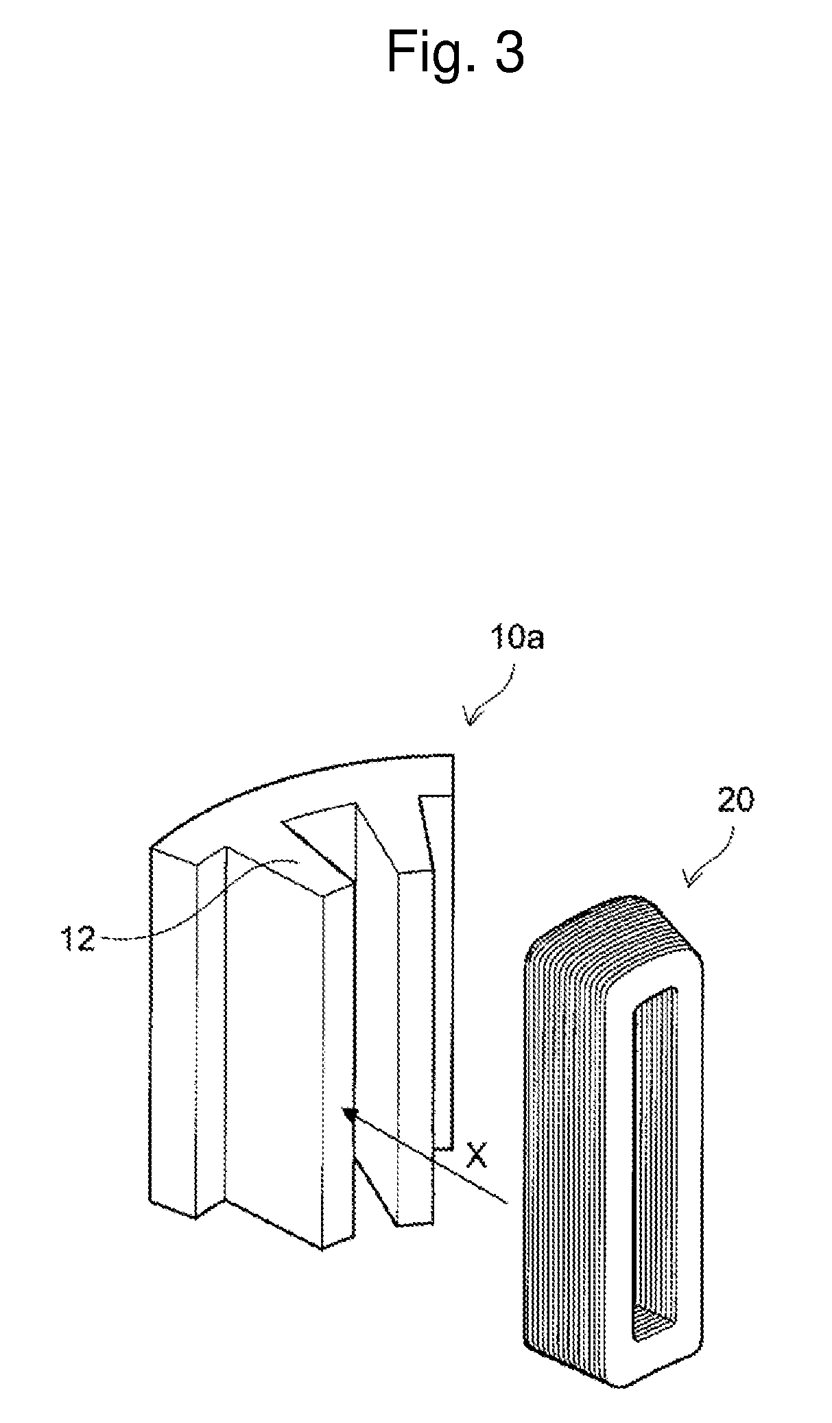
If the strength of the stator core is deteriorated, a breakage such as chipping, cracking, or a scratch is easily generated in the stator core (in particular, a tooth thereof) when a coil is mounted on a tooth of the stator core in a post-process.
That is, in a step of mounting the coil on the tooth, a load is applied to the stator core when the coil is wound or bent, so that the aforementioned breakage may be generated.

Method used


Image

  • Production method for stator
  • Production method for stator
  • Production method for stator

Examples


Example

Example 1

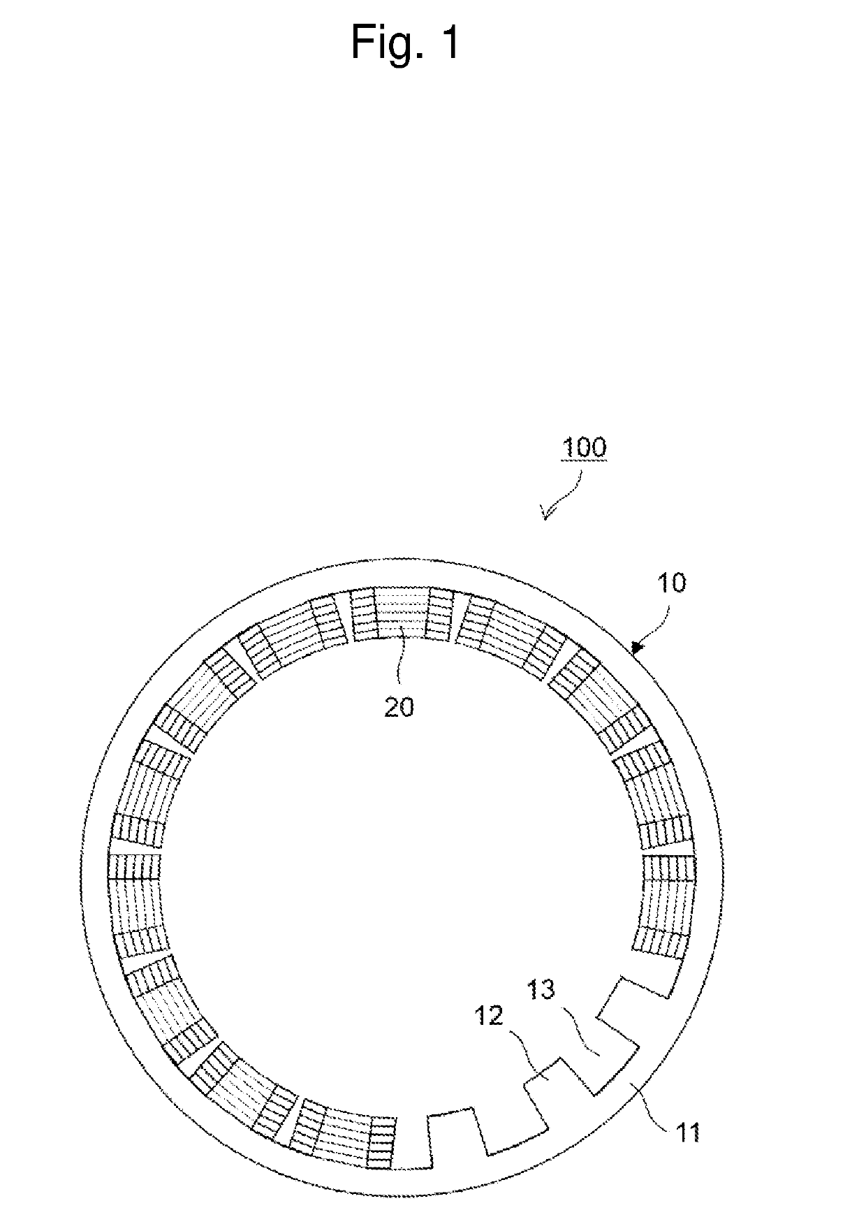
[0061]An amorphous plate (thickness: 25 μm, crystallization temperature: 391° C., degree of crystallinity: 0%, tensile strength: 1861 MN / m2) was prepared, the amorphous plate was punched with use of a press die, and thus, stator core plates were produced. Since the amorphous-based soft magnetic material was used for the stator core plates, the degree of crystallinity thereof was 0%. The crystallization temperature was identified by measurement of the exothermic reaction starting temperature with use of a differential scanning calorimeter (DSC) under the condition in which the heating rate was 0.67 Ks−1.

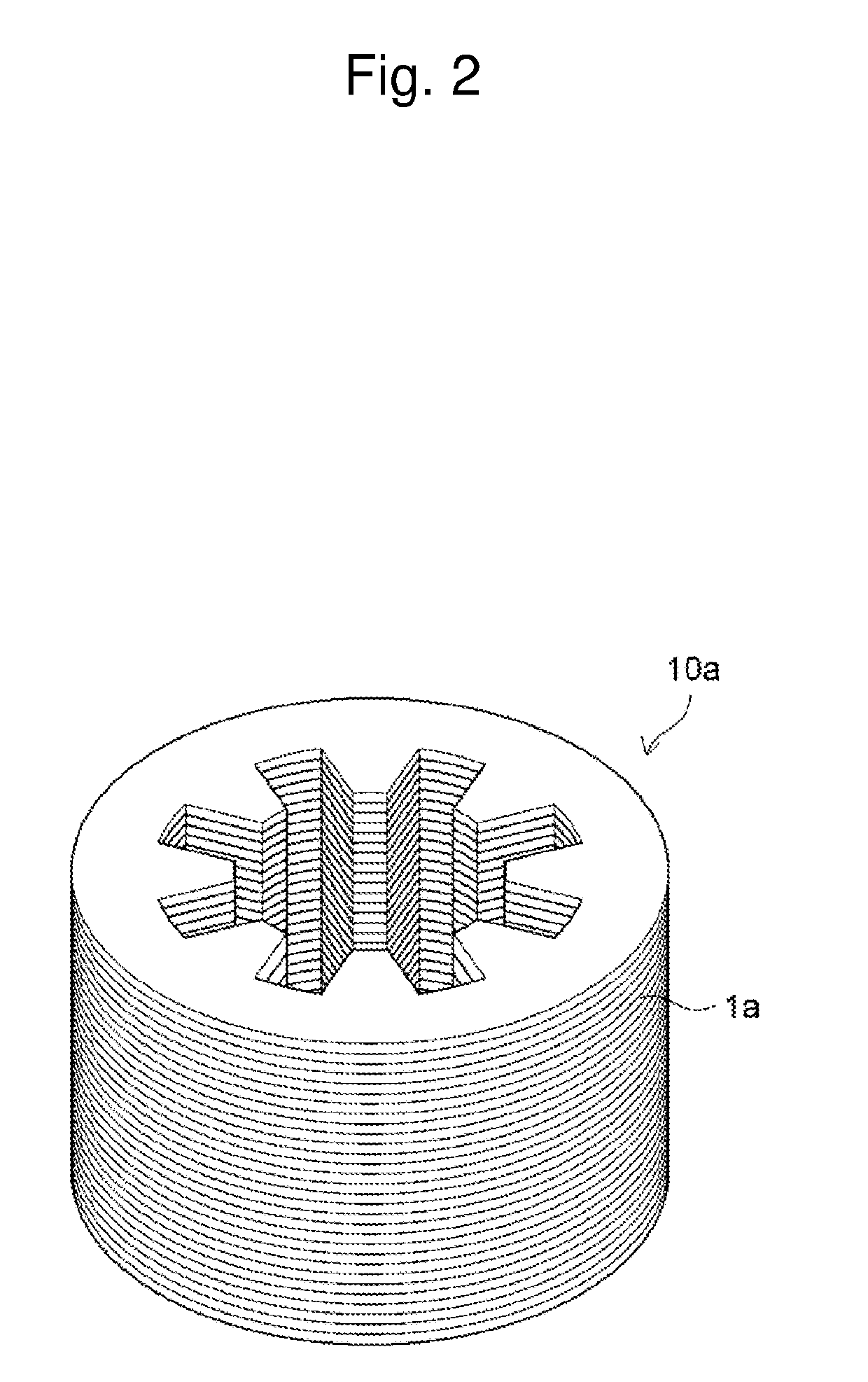
[0062]Next, the stator core plates were stacked, were fastened with bolts, and thus, a stacked body was produced. In addition, insulators were inserted in slots of the stacked body.

[0063]Next, as illustrated in FIGS. 4(A) and 4(B), a plurality of stacked segments were inserted in the slots, the lead portions thereof were bent, and the adjacent lead portions were welded togethe

Example

Example 2

[0066]A nanocrystal plate (thickness: 25 μm, degree of crystallinity: 90%, tensile strength: 1820 MN / m2) was prepared, and the nanocrystal plate was punched into a stator core plate with use of a press die.

[0067]The degree of crystallinity thereof was calculated, by Expression (1), from a caloric value (J / g) of crystallization measured with a differential scanning calorimeter (DSC). As the “amorphous-based soft magnetic material which corresponds to a soft magnetic material to be measured”, an amorphous plate (i.e. the amorphous plate used in Example 1) before heat treatment of the nanocrystal plate (heat treatment for generating a nanocrystal) was used.

[0068]The stator core plates thus obtained were used and heated at 430° C. for three seconds. Except for this, the same process as Example 1 was performed to produce a stator.

[0069]In the present example, no breakage was generated when the coils were mounted, and a stator having the saturation magnetization improved by the


PUM

PropertyMeasurementUnit
Degree of crystallinityaaaaaaaaaa
Temperatureaaaaaaaaaa
Frequencyaaaaaaaaaa

Abstract

An object of the present disclosure is to provide a production method for a stator in which a breakage of the stator core can be prevented when coils are mounted thereon. The present embodiment is a production method for a stator that includes a stator core having a tooth and includes a coil wound around the tooth. The method includes: a step of preparing a stacked body which has the tooth and in which a plurality of plate-like soft magnetic materials each including an amorphous structure are stacked; a step of mounting the coil on the tooth; and a step of, after the coil is mounted, heating the stacked body to a temperature equal to or higher than a crystallization temperature of the soft magnetic materials.

Description


Claims


Application Information

Patent Timeline
Owner TOYOTA JIDOSHA KK
Why Eureka
Try Eureka