Interior door handle emergency lockdown apparatus, system, mobile application, and method thereof

a technology for interior doors and emergency lockdown, applied in the field of electronic door locksets, can solve the problems of poor solution, user may not have a regular key, and school budgets are not typically sufficient for extravagant security systems

Active Publication Date: 2019-08-01
CAHILL JEFF
View PDF0 Cites 3 Cited by
  • Summary
  • Abstract
  • Description
  • Claims
  • Application Information

AI Technical Summary

Benefits of technology

The technical effect that this innovation provides are improved security measures against unauthorized access or intrusion into buildings through doors with special locks installed inside them. These improvements can help reduce damage caused during emergency situations such as fires or terrorist attacks.

Problems solved by technology

The technical problem addressed in this patented text rels specifically towards finding ways to securely disable electronic loves without requiring users to carry bulky equipment like keys at all times when needed.

Method used


Image

  • Interior door handle emergency lockdown apparatus, system, mobile application, and method thereof
  • Interior door handle emergency lockdown apparatus, system, mobile application, and method thereof
  • Interior door handle emergency lockdown apparatus, system, mobile application, and method thereof

Examples


Embodiment Construction

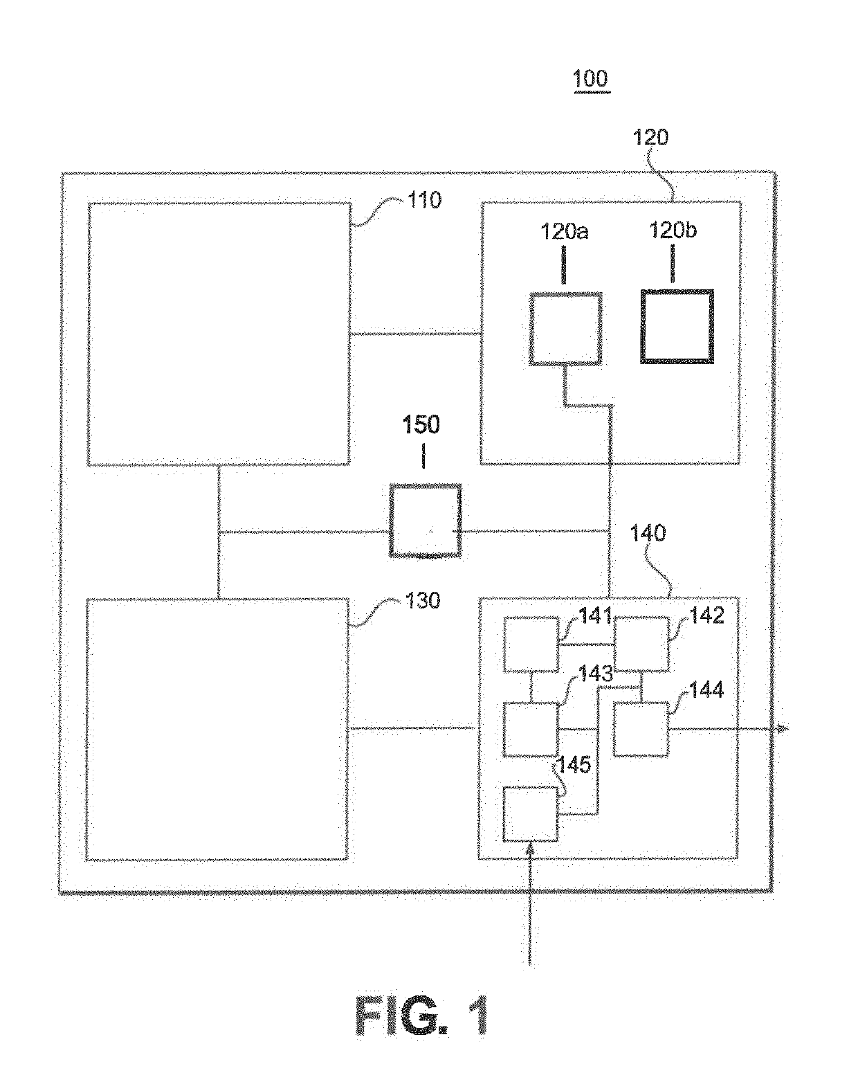
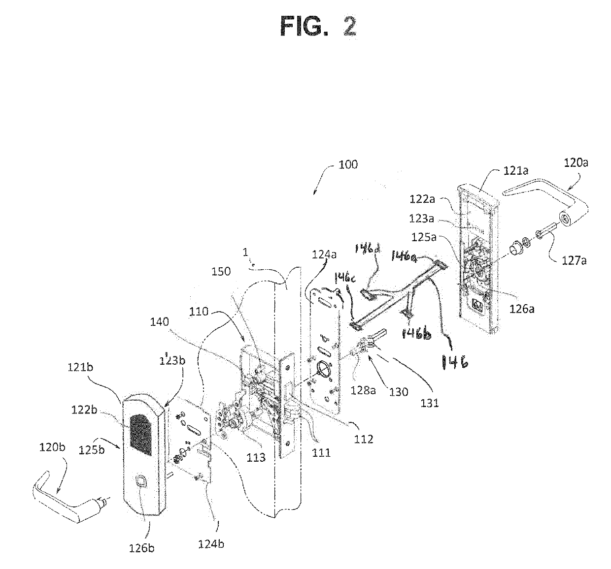
[0024]Various example embodiments will now be described more fully with reference to the accompanying drawings in which some example embodiments are illustrated. In the figures, the thicknesses of lines, layers and / or regions may be exaggerated for clarity.

[0025]Accordingly, while example embodiments are capable of various modifications and alternative forms, embodiments thereof are shown by way of example in the figures and will herein be described in detail. It should be understood, however, that there is no intent to limit example embodiments to the particular forms disclosed, but on the contrary, example embodiments are to cover all modifications, equivalents, and alternatives falling within the scope of the disclosure. Like numbers refer to like or similar elements throughout the description of the figures.

[0026]It will be understood that when an element is referred to as being “connected” or “coupled” to another element, it can be directly connected or coupled to the other elem


PUM


Abstract

An electronic lockset mounted on a door, the electronic lockset including a lock comprising at least one of a latch bolt and a deadbolt to prevent the door from opening when the lock is in a locked state, an interior handle to open the door when the lock is in an unlocked state, a sensor to sense a manipulation of the interior handle, a printed circuit board (PCB) to receive information sensed by the sensor regarding the manipulation of the interior handle, and a motor to move the at least one of the latch bolt and the deadbolt in response to a signal received by the PCB directed to the information regarding the manipulation of the interior handle.

Description


Claims


Application Information

Patent Timeline
Owner CAHILL JEFF
Why Eureka
Try Eureka