Control system for a power generation system
a power generation system and control system technology, applied in the direction of controllers with particular characteristics, dc source parallel operation, instruments, etc., can solve the problems of large disturbance of total current, inability to appropriately compensate, and potential spoilage of pots, so as to achieve the effect of maintaining regulation
- Summary
- Abstract
- Description
- Claims
- Application Information
AI Technical Summary
Benefits of technology
Problems solved by technology
Method used
Image

Examples
first embodiment
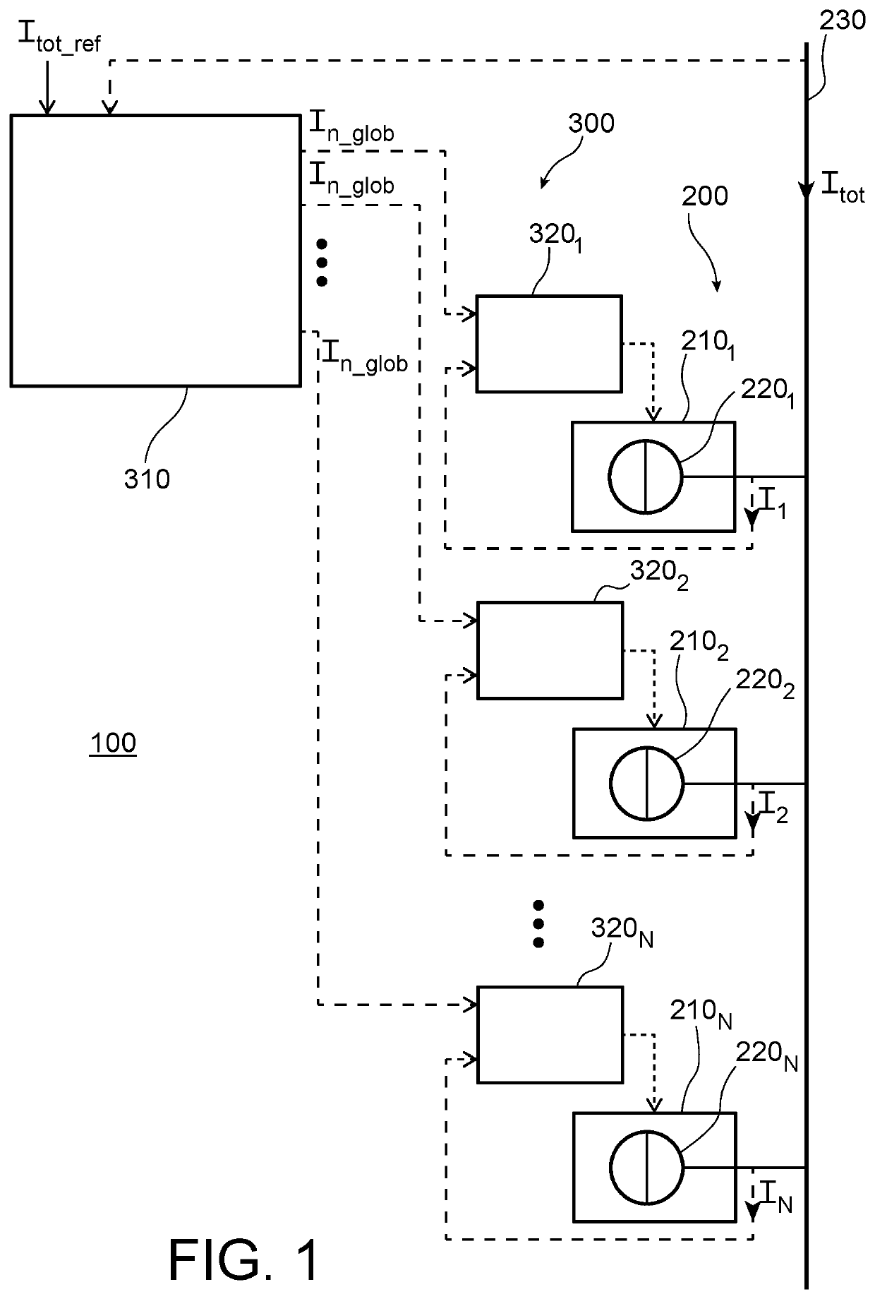
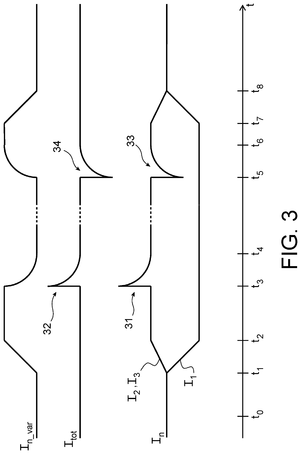
FIG. 3 is a timing diagram illustrating how the power system 100 as described above functions. Time t is represented in abscissa and the intensity of each current is represented in ordinate. Note that the intensity scale is not the same for all currents but only aims at showing time evolution of each current with respect to the others. For this figure, it is considered a power generation system 200 with three elementary power groups 210 (N=3), dedicated to deliver a total current of 300 kA (Itot_ref=300 kA). It is assumed that at time to, the elementary power sources 220 of all elementary power groups 210 are in the ON-state and each generate a same elementary current In (In=I1=I2=I3=100 kA). For some reasons, it is desired to stop the elementary power group 2101 for a certain period. Then, at time t1, elementary current I1 starts to decrease until it reaches zero at time t2. This decrease is for example managed by setting a predetermined decreasing local current set point I1_loc. The
second embodiment
[0049]In a second embodiment, the correction signal Scorr does not take into account all elementary currents In but only those of elementary power sources 220 in the ON-state in the new scenario associated with a local current control system 320n working in the local mode. The above formulas become:
Scorr=∑n=1NON_loc(Itot_refNON-In) / (NON-NON_loc)andScorr=∑n=1NON_loc(In_fix-In) / (NON_glob)
[0050]FIG. 6 is a timing diagram similar to that of FIG. 3 illustrating how the power system 400 according to a first embodiment of the invention functions. The same assumptions as for the timing diagram of FIG. 3 are considered. At time to, the correction unit works in the steady state. From time t0 to time t2, the power system 400 shows a same working. In particular, the variable set point In_var increases from 0 to 50 kA. However, when the elementary power source 2201 switches to the OFF-state at time t3, the scenario management unit 514 detects the change and triggers the transitory state by mean
PUM
 Abstract
Description
Claims
Application Information
 - R&D Engineer
- R&D Manager
- IP Professional
- Industry Leading Data Capabilities
- Powerful AI technology
- Patent DNA Extraction
Browse by: Latest US Patents, China's latest patents, Technical Efficacy Thesaurus, Application Domain, Technology Topic.
© 2024 PatSnap. All rights reserved.Legal|Privacy policy|Modern Slavery Act Transparency Statement|Sitemap