Lens driving device, camera module and optical device

a technology of optical devices and driving devices, which is applied in the direction of camera focusing arrangement, printers, instruments, etc., can solve the problems of affecting the lens, the filter, the image sensor, etc., and achieve the reduction of the size of the optical device bezel, the reduction of the terminal size, and the widening of the display panel

Active Publication Date: 2020-04-09
LG INNOTEK CO LTD
View PDF0 Cites 7 Cited by
  • Summary
  • Abstract
  • Description
  • Claims
  • Application Information

AI Technical Summary

Benefits of technology

The present technology allows for capturing any particles caused during machining processes without being scattered back into other areas around them. It achieves this by fixing terminals with respectable position within holes formed at the top surface of the housing while allowing light rays passing through. This reduces the overall thickness of the apparatus'beamformers and improves image quality. Additionally, there has been developed a stable mount system where the covers used have raised parts attached to their edges, preventing separation when subjected to forces such as gravity. Overall, these technical improvements improve performance and functionality of the equipment involved in manufacture.

Problems solved by technology

This patented describes different technical features for improving the performance characteristics (performance) of cameras used in electronic devices such as smartphones that use this technology.

Method used


Image

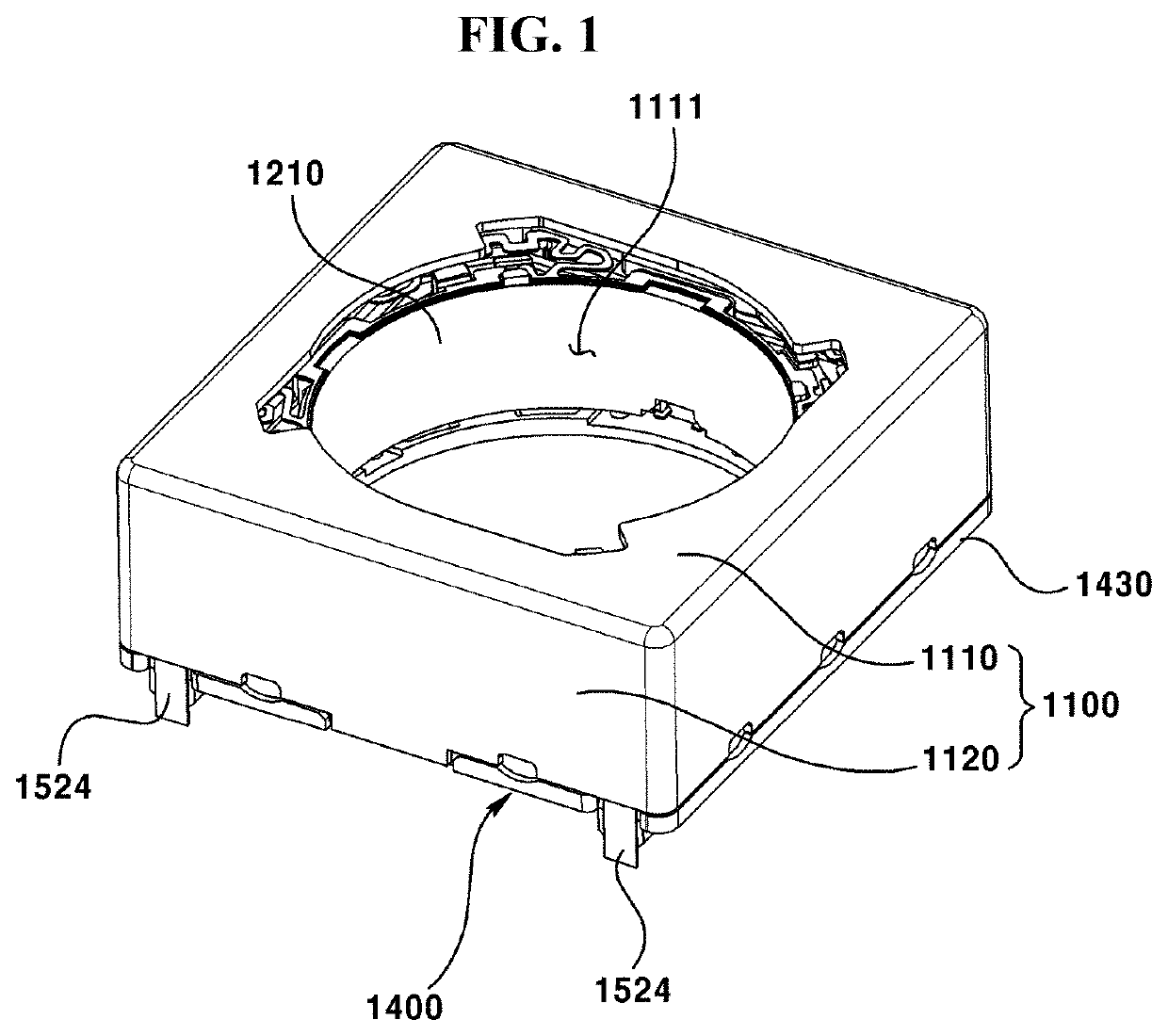
  • Lens driving device, camera module and optical device
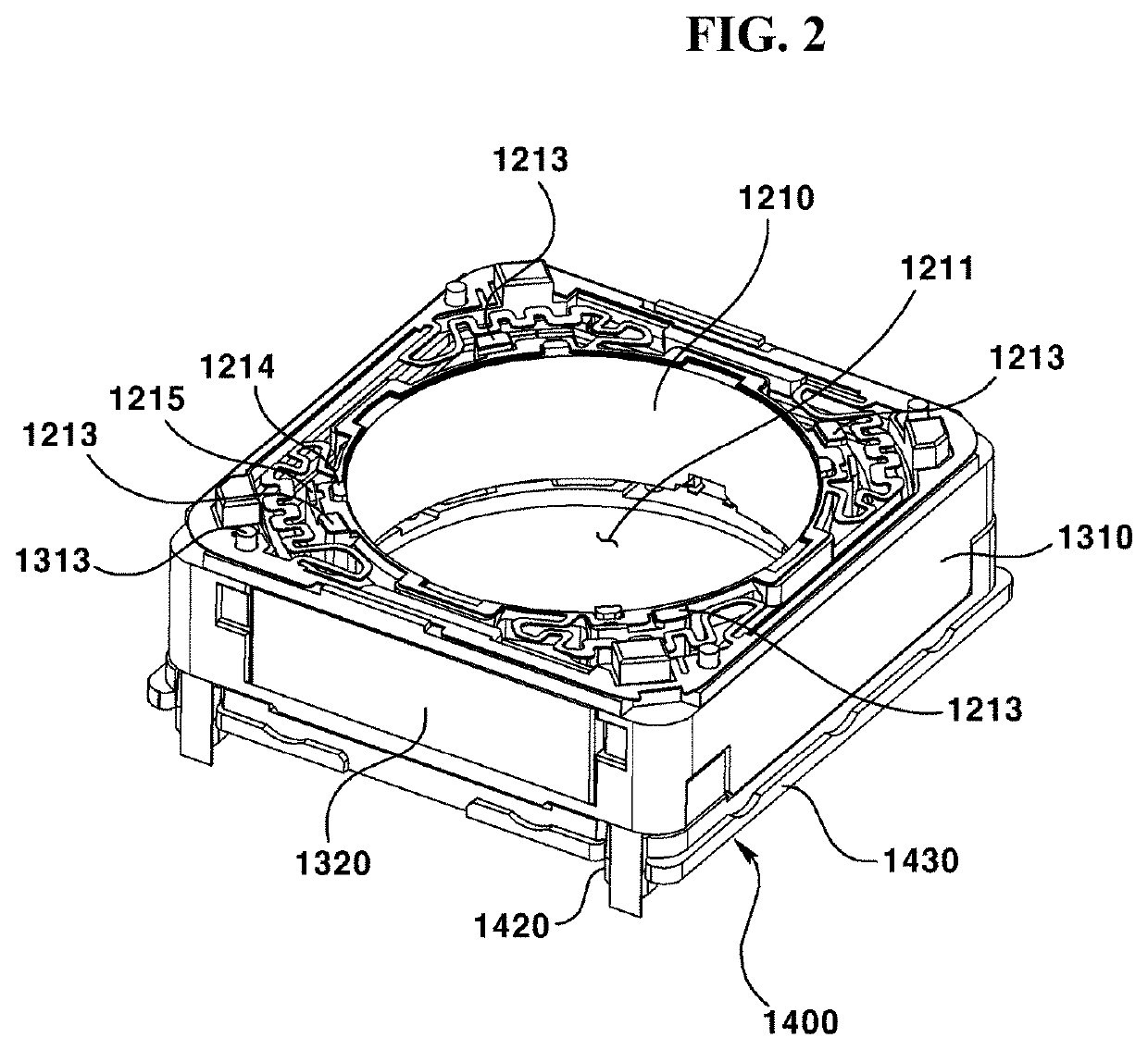
  • Lens driving device, camera module and optical device
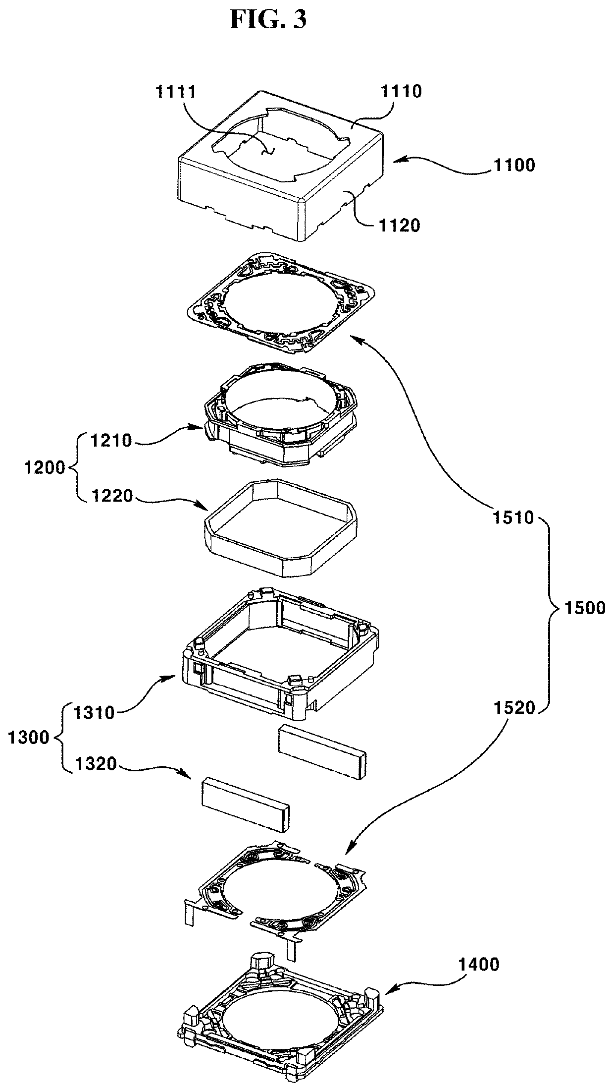
  • Lens driving device, camera module and optical device

Examples


first embodiment

[0011]The first embodiment is intended to provide a lens driving device including a bobbin having a structure for capturing foreign matters.

[0012]It is also intended to provide a lens driving device having a structure in which captured foreign matters will not be re-scattered again.

second embodiment

[0013]The second embodiment is intended to provide a lens driving device including a structure in which deformation of a terminal is minimized.

[0014]Also, it is intended to provide a camera module including the lens driving device.

third embodiment

[0015]The third embodiment is intended to provide a lens driving device capable of performing an autofocus function and, at the same time, reducing the bezel size of the optical device by shifting the optical axis of the lens module from the center, a camera module including the lens driving device, and an optical device including the camera module.


PUM


Abstract

The first embodiment of the present invention relates to a lens driving device comprising: a cover including an upper plate and a lateral plate extending from the upper plate; a bobbin arranged to move in a first direction within the cover; a coil arranged at the bobbin; a magnet which is arranged at the cover and faces the coil; and a base which is arranged below the bobbin and coupled to the cover, wherein the bobbin includes: a first surface facing the upper plate of the cover; a second surface which faces upwards and is arranged lower than the first surface; a first protrusion which is arranged at the first surface of the bobbin and overlapped with the upper plate of the cover in a first direction; and a groove concavely formed downwards on the second surface of the bobbin.

Description


Claims


Application Information

Patent Timeline
Owner LG INNOTEK CO LTD
Why Eureka
Try Eureka