Power source switch control device

Active Publication Date: 2020-07-09
YAZAKI CORP
View PDF0 Cites 1 Cited by
  • Summary
  • Abstract
  • Description
  • Claims
  • Application Information

AI Technical Summary

Benefits of technology

Problems solved by technology

The technical problem addressed by this patent is how to improve the detection of faulty switching elements in a semiconductor relay that controls power sources in an electric circuit without compromising its performance.

Method used


Image

  • Power source switch control device
  • Power source switch control device
  • Power source switch control device

Examples


embodiment

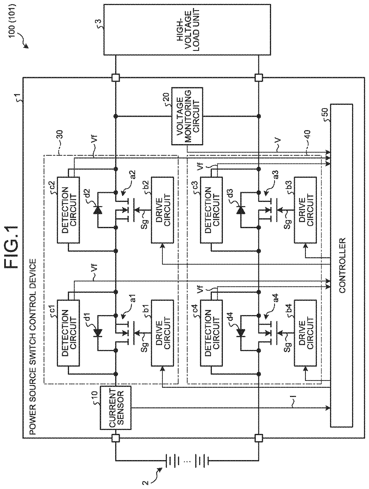
[0024]The following describes a power source switch control device 1 according to the embodiment. For example, a vehicle such as an electric vehicle or a hybrid electric vehicle is sometimes provided with a high-voltage system 100 having a function to drive a high-voltage load unit 3 by supplying power source electricity from a high-voltage battery 2 to the high-voltage load unit 3 and a function to charge the high-voltage battery 2 by supplying regenerative electricity from the high-voltage load unit 3 to the high-voltage battery 2. The high-voltage system 100 includes the high-voltage battery 2 as a direct-current power source, the high-voltage load unit 3 as a load unit, and the power source switch control device 1. The high-voltage system 100 functions as a power circuit 101 in which the high-voltage battery 2 and the high-voltage load unit 3 are electrically connected with each other through the power source switch control device 1.

[0025]The high-voltage battery 2 is a high-voltag


PUM


Abstract

A power source switch control device includes a detection circuit, a detection circuit, a detection circuit, and a detection circuit. The detection circuit detects forward voltage of a body diode of a FET, and the detection circuit detects forward voltage of a body diode of a FET. The detection circuit detects forward voltage of a body diode of a FET, and the detection circuit detects forward voltage of a body diode of a FET. A controller determines whether a defect of a power circuit has occurred based on results of the detection by the detection circuits to. Accordingly, the power source switch control device can appropriately detect defect of a switching element of a power source.

Description


Claims


Application Information

Patent Timeline
Owner YAZAKI CORP
Why Eureka
Try Eureka