Robot and method for estimating direction on basis of vanishing point in low light image

a low light image and vanishing point technology, applied in image enhancement, programme control, instruments, etc., can solve the problems of not being able to remove such a hindrance from a space with a transient population, not being able to accurately identify, and difficult to install such marks in every spa

Pending Publication Date: 2020-09-10
LG ELECTRONICS INC
View PDF25 Cites 1 Cited by
  • Summary
  • Abstract
  • Description
  • Claims
  • Application Information

AI Technical Summary

Benefits of technology

The present invention provides a method for estimating the orientation or position of a robotic arm by analyzing images taken at different angles. This allows for accurate estimation even with low light conditions. Additionally, this technology can be applied to multiple manneck frames structures without any errors caused by changes in materials being placed within them.

Problems solved by technology

The technical problem addressed in this patent is how to accurately locate and track a mobile robot's position within a specific area without requiring markers attached during navigation.

Method used


Image

  • Robot and method for estimating direction on basis of vanishing point in low light image
  • Robot and method for estimating direction on basis of vanishing point in low light image
  • Robot and method for estimating direction on basis of vanishing point in low light image

Examples


Embodiment Construction

[0035]Hereinafter, exemplary embodiments of the present invention will be described in detail with reference to the accompanying drawings so that those of ordinary skill in the art to which the present invention pertains may readily implement the present invention. The present invention may be embodied in various different forms and is not limited to the embodiments set forth herein.

[0036]To clearly describe the present invention, parts that are irrelevant to the description will be omitted, and the same or similar elements will be designated by the same reference numerals throughout the specification. Also, some embodiments of the present invention will be described in detail with reference to exemplary drawings. In adding reference numerals to elements, identical elements are referred to by the same reference numeral as possible even when the elements are depicted in different drawings. In describing the present invention, when it is determined that the detailed description of a know


PUM


Abstract

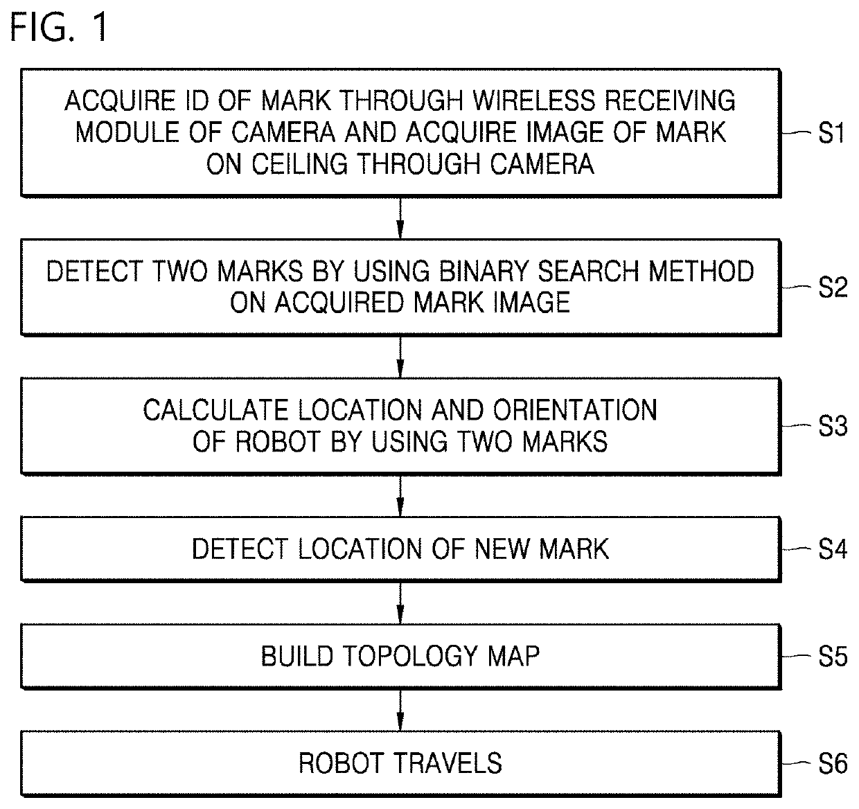
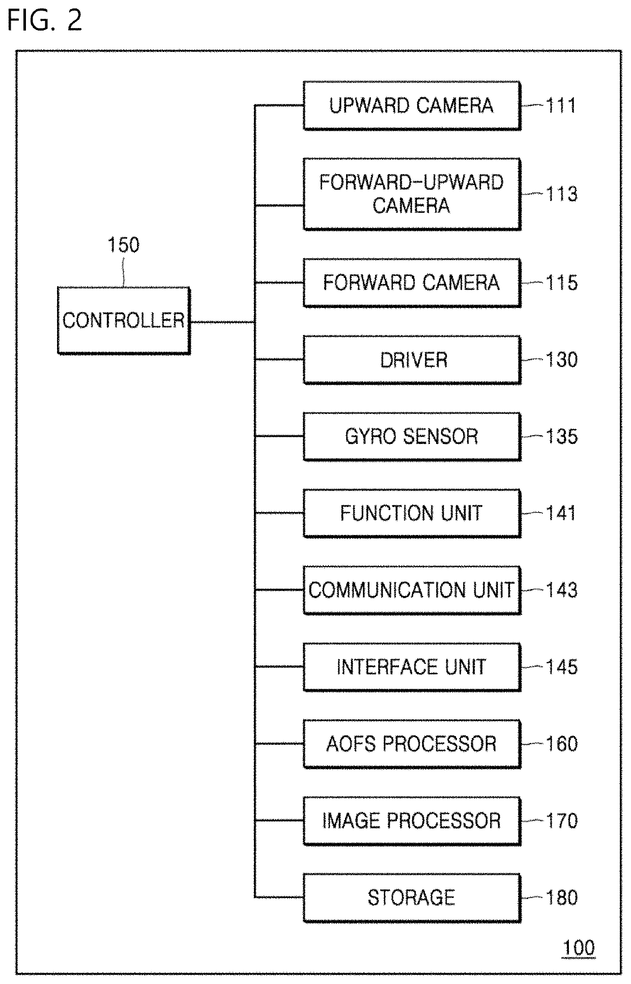
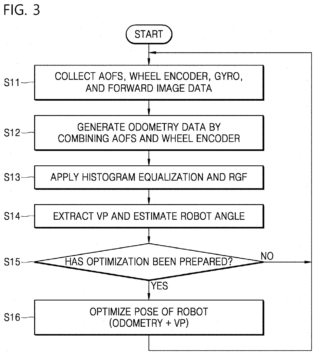
The present invention relates to a robot and method for estimating an orientation on the basis of a vanishing point in a low-luminance image, and the robot for estimating an orientation on the basis of a vanishing point in a low-luminance image according to an embodiment of the present invention includes a camera unit configured to capture an image of at least one of a forward area and an upward area of the robot and an image processor configured to extract line segments from a first image captured by the camera unit by applying histogram equalization and a rolling guidance filter to the first image, calculate a vanishing point on the basis of the line segments, and estimate a global angle of the robot corresponding to the vanishing point.

Description


Claims


Application Information

Patent Timeline
Owner LG ELECTRONICS INC
Why Eureka
Try Eureka