Oil and aqueous phase separator

a technology of oil and aqueous phase, applied in the direction of liquid separation, water cleaning, construction, etc., can solve the problems of poor versatility in the geometry or configuration of the oil separator, high cost involved in the removal of oil in these bodies of water, and difficult handling, so as to achieve the effect of improving the separation properties

Active Publication Date: 2021-02-11
YPF TECHA +1
View PDF0 Cites 1 Cited by
  • Summary
  • Abstract
  • Description
  • Claims
  • Application Information

AI Technical Summary

Benefits of technology

The present invention relates to a new type of device that can separate mixtures of liquids like oil and water by creating a special kind of film called a "hydrophobic membrane". This makes it very useful because it has many advantages over existing methods. It's easy to use and can be used to remove harmful substances from tank floors and ponds. Additionally, this device could be scaled up to cover different areas where there are mixed fluids.

Problems solved by technology

This patent describes various technical problem addressed in the patent text relating to the pollution caused by oil spills on lakes and oceans. Current methods involve removing oil and hydrocarbon substances from the water through physical scrapings or chemical treatments, which require expensive equipment and consume significant amounts of time. There is a need for a device that can adapt to different geometric configurations while maintaining ease of use and economy.

Method used


Image

  • Oil and aqueous phase separator
  • Oil and aqueous phase separator
  • Oil and aqueous phase separator

Examples


Embodiment Construction

[0062]The present invention will be described in greater detail below with reference to the appended figures that illustrate embodiments of the invention by way of example which should not be construed as limiting thereof.

[0063]For the purposes of the present invention, the terms “oil phase”, “oily phase”, “organic phase”, “water immiscible phase”, “oil and / or hydrocarbon derivatives thereof” or derivative terms thereof are used interchangeably to designate a liquid phase that is highly immiscible with water.

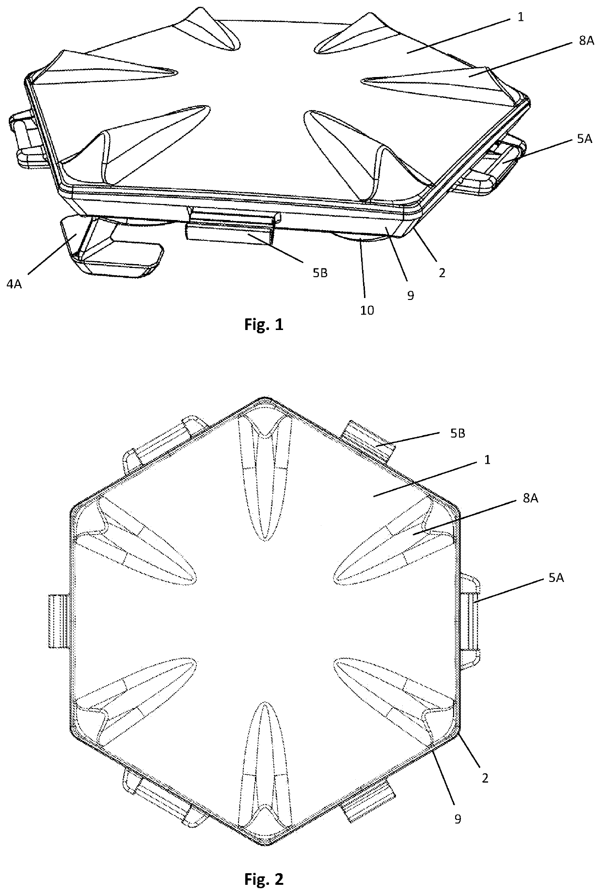
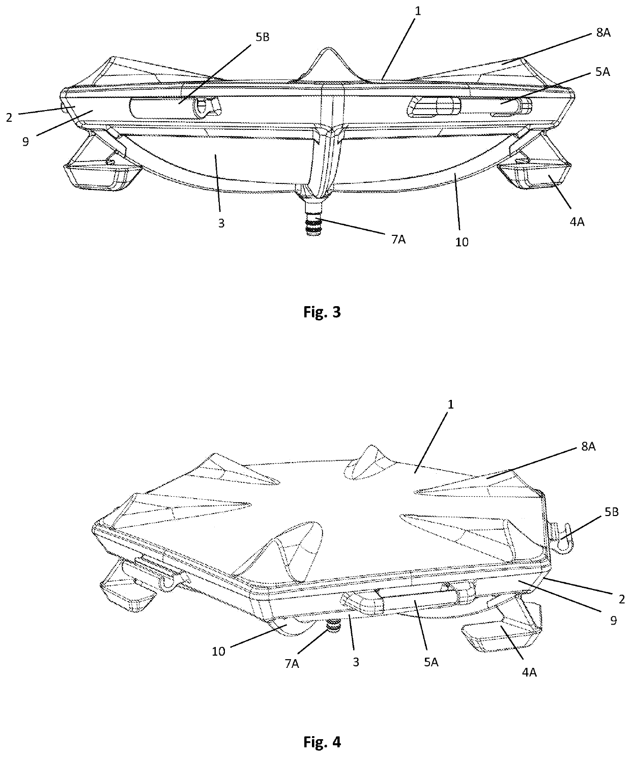
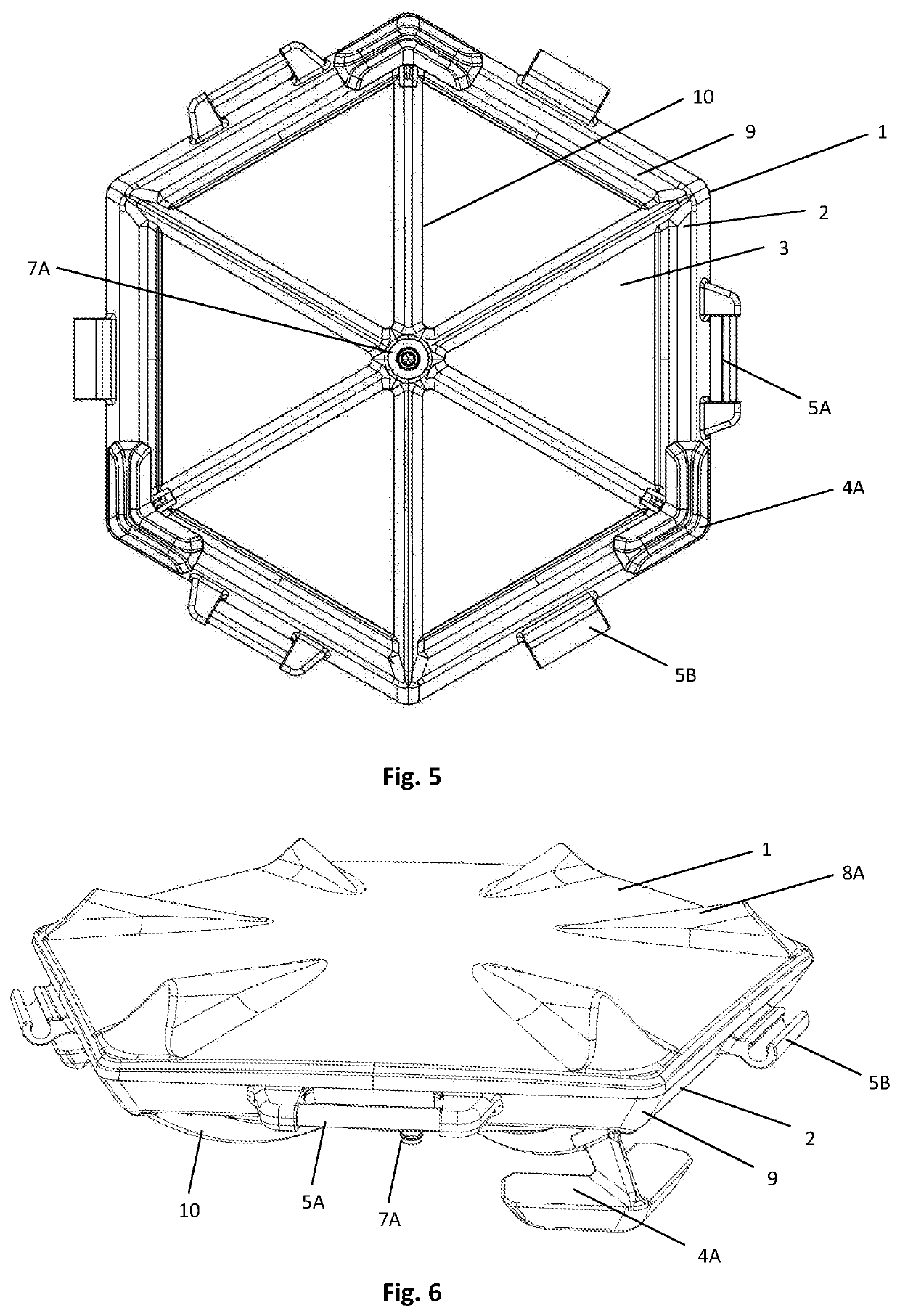
[0064]FIGS. 1 to 8 show several views of an embodiment of the phase separator device of the present invention, where said device comprises a lid 1, a basket 2, an hydrophobic mesh 3, a plurality of floats 4A, fitting means 5A, 5B, a perimetral housing 6, a discharging means 7A, protrusions 8A, a frame 9 and supporting arms 10.

[0065]It can be appreciated in said FIGS. 1 to 8 that the lid 1 has a horizontal cross section of hexagonal shape and, in each of the hexagon vertices, a pr


PUM


Abstract

Oil and aqueous phase separator device comprising: a basket that comprises a frame having a plurality of supporting arms and fitting means for linking to other phase separator devices; a top lid of the basket; a hydrophobic mesh linked to the basket and supported by the plurality of supporting arms; a plurality of floats linked to the frame of the basket; a housing for an additional float formed on the upper edge of the frame of the basket; and discharging means linked to the basket.

Description


Claims


Application Information

Patent Timeline
Owner YPF TECHA
Why Eureka
Try Eureka