Construction machine with measuring system and construction site measuring system

Pending Publication Date: 2021-08-19
LEICA GEOSYST TECH +2
View PDF0 Cites 2 Cited by
  • Summary
  • Abstract
  • Description
  • Claims
  • Application Information

AI Technical Summary

Benefits of technology

[0008]It is therefore an object of the invention to provide a construction machine with an improved measuring system, or respectively, to provide an improved construction site measuring system. A construction machine or a construction site measuring system according to the invention allows fo

Problems solved by technology

However, downsides of the prior art are a slow scan and/or detection of the environment of the construction machin

Method used


Image

  • Construction machine with measuring system and construction site measuring system
  • Construction machine with measuring system and construction site measuring system
  • Construction machine with measuring system and construction site measuring system

Examples


Embodiment Construction

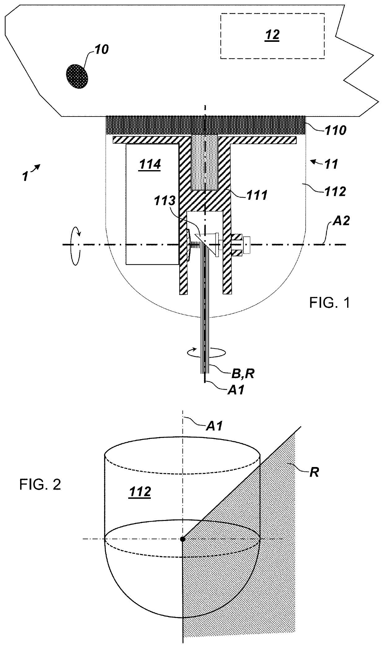
[0047]FIG. 1 shows a schematic overview of one embodiment of a measuring unit comprised by a measuring system according to this invention. The measuring unit 1 comprises a first camera 10 and a first LiDAR scanner 11 configured for rotating a first measuring beam B around a first axis A1 and around a second axis A2. In a preferred embodiment, the axes A1 and A2 are perpendicular and are crossing in the impinging point of the measuring beam B on the deflector.

[0048]The LiDAR scanner 11 is configured to rotate the beam B around both axes with a rotating speed of at least 0.5 Hz in each case. What follows is a scanning pattern that captures a full range of the LiDAR scanner 11 (which is shown in detail in FIG. 2) in a very short time. Said range R of the first LiDAR scanner 11 and a field of view (FOV) of the first camera 10 together form a first detection range of the measuring unit 1, where first measuring data are generated. In particular, the measuring data comprise angle data with re


PUM


Abstract

A construction machine comprising a chassis, a steering, and a powertrain for driving the construction machine by the chassis, an earth-moving tool for working a terrain, and a measuring system having a first measuring unit configured for generating first measuring data in a first detection range and comprising at least a first camera and a first LiDAR scanner configured for rotating a first measuring beam around a first axis and around a second axis non-parallel to the first axis with a rotating speed of at least 0.5 Hz with respect to each axis, an interface connecting the first measuring unit to a computer configured for, based on the first measuring data, at least one of generating a three-dimensional model of the terrain within the first detection range, identifying an obstacle or a person within the first detection range, and controlling the steering, the powertrain, and/or the earth-moving tool.

Description


Claims


Application Information

Patent Timeline
Owner LEICA GEOSYST TECH
Why Eureka
Try Eureka