Expansion installation and installation for obtaining electrical energy from heat

Pending Publication Date: 2021-11-25
BITZER KUEHLMASCHINENBAU GMBH
View PDF0 Cites 0 Cited by
  • Summary
  • Abstract
  • Description
  • Claims
  • Application Information

AI Technical Summary

Benefits of technology

[0039]In order to arrange the stator of the sensor generator in a manner that is as easy as possible to maintain and where appropriate also easy to retrofit, it is preferably provided for the stator of the sensor generator to be held on a casing element, in particular a casing element that is demountable from the overall casing.
[0040]In this way, it is possible to perform maintenance in a particularly simple manner and where appropriate also to retrofit the sensor generator in a simple manner.
[0041]So that the sensor signal can be directed in a simple manner to a controller for the expansion installation, it is preferably provided for the casing element to be provided with an electrical terminal feedthrough such that the sensor signal can be directed out of the overall casing in a simple manner.

Problems solved by technology

However, evaluation of a current is more complex since it has to flow through a load and is thus no longer proportional to the speed of rotation of the generator.

Method used


Image

  • Expansion installation and installation for obtaining electrical energy from heat
  • Expansion installation and installation for obtaining electrical energy from heat
  • Expansion installation and installation for obtaining electrical energy from heat

Examples


Example

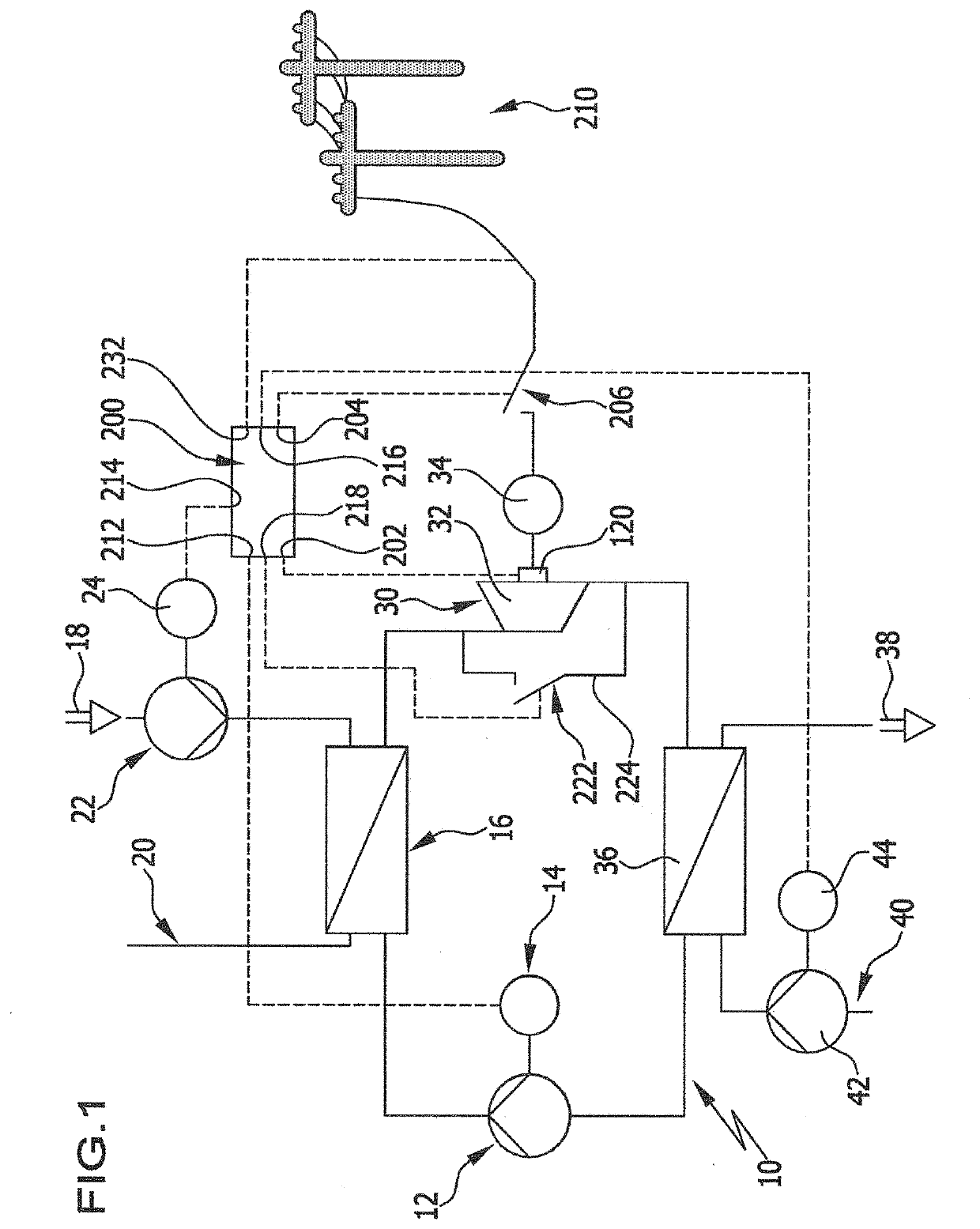
[0193]The fifth exemplary embodiment operates such that—as described in conjunction with the first exemplary embodiment—the generator 34 can be connected up by the power switch 206 if it delivers AC voltage at a frequency corresponding to the grid frequency of the grid 210.

[0194]In addition to connecting the generator 34 up to the grid 210 by means of the power switch 206, it is also possible for the connection switch 260 to connect the capacitor set 242 to the stator windings 254, 256 and 258 in parallel, wherein the capacitor set 242, with its capacitors 244, 246 and 248, serves to make an adaptation to the output as regards reactive and active power.

[0195]In this case, the controller 200′ closes the connection switch 260 if the power switch 206 is likewise closed and so the generator 34 outputs electrical energy to the grid 210. However, if the power switch 206 is opened the connection switch 260 initially continues to remain closed.

[0196]In addition, the resistor connection switch


PUM


Abstract

In order to improve an expansion installation for obtaining electrical energy from heat by means of a thermodynamic circulation procedure, comprising an expansion device, which is operated by an expanding working medium of the thermodynamic circulation procedure, and a generator driven by the expansion device, it is proposed that the expansion installation should be provided with a rotational speed sensor, which is coupled to a shaft of the expansion installation that rotates proportionally to a rotor of the generator, and which takes the form of an electrical sensor generator that generates an electrical sensor signal.

Description


Claims


Application Information

Patent Timeline
Owner BITZER KUEHLMASCHINENBAU GMBH
Why Eureka
Try Eureka