Laser emitting system

Pending Publication Date: 2021-12-09
CHENGDU SUPERXON COMM TECH CO LTD
View PDF0 Cites 0 Cited by
  • Summary
  • Abstract
  • Description
  • Claims
  • Application Information

AI Technical Summary

Benefits of technology

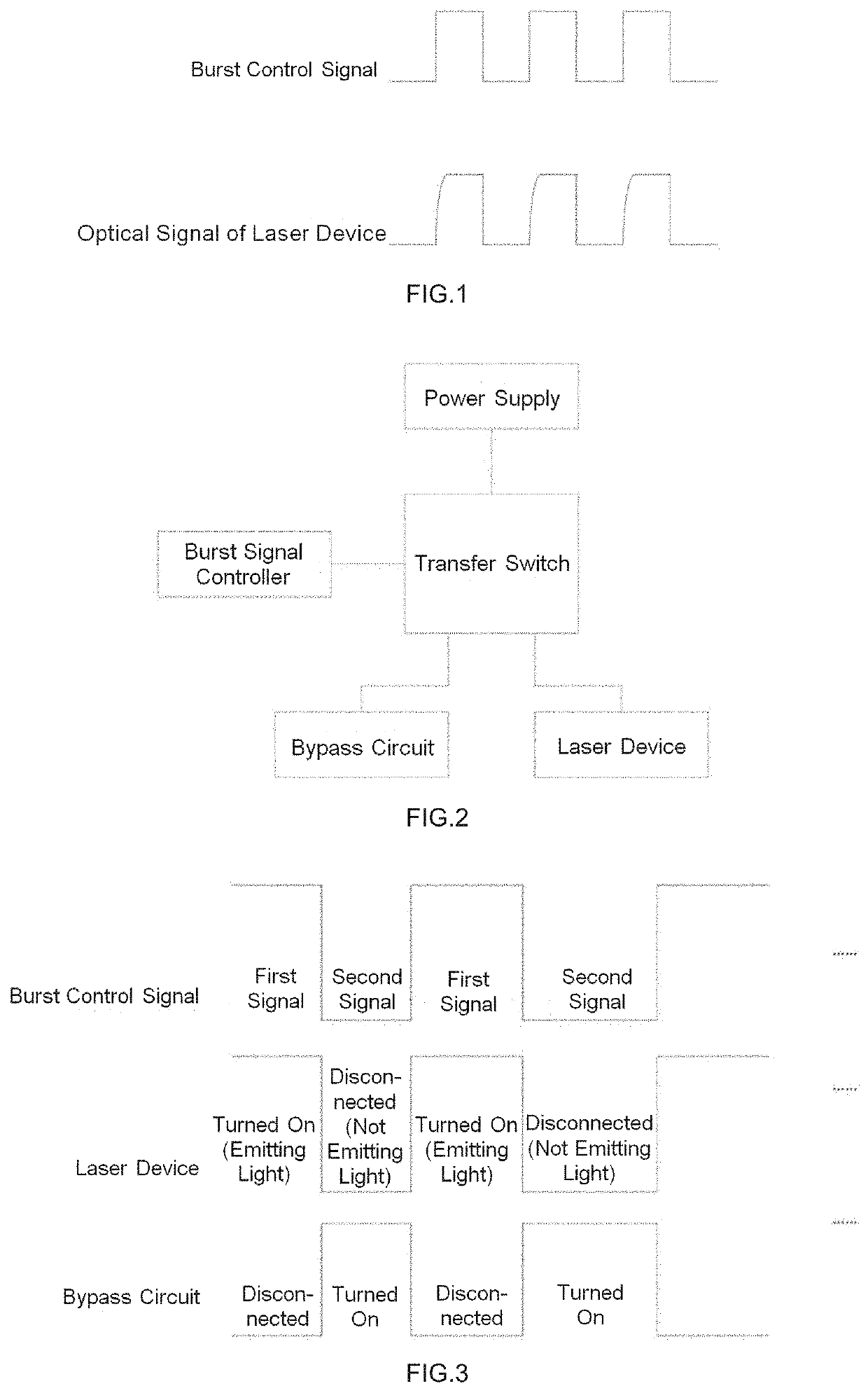
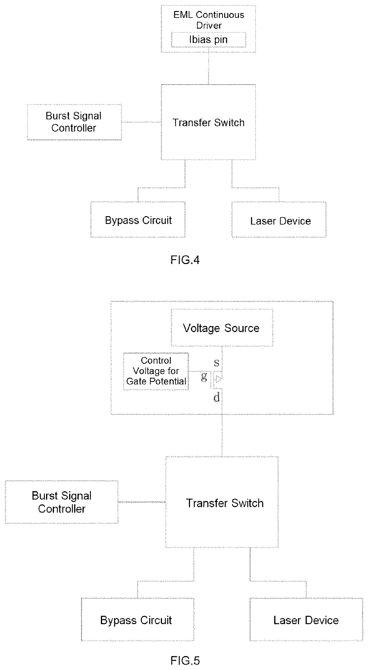
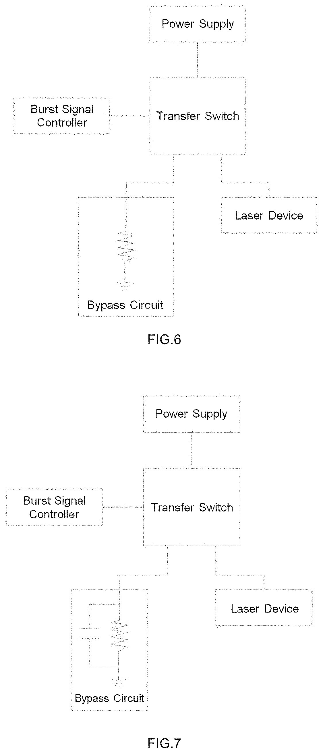
[0006]In order to solve the above-described technical problem, the technical solution provided by the present disclosure includes a laser emitting system, comprising a burst signal controller, a transfer switch, a power supply, a laser device and a bypass circuit, wherein the bu

Problems solved by technology

In addition, the laser device itsel

Method used


Image

  • Laser emitting system
  • Laser emitting system
  • Laser emitting system

Examples


Embodiment Construction

[0031]The technical solutions in the embodiments of the present disclosure will be clearly and completely described below with reference to the drawings of the embodiments of the present disclosure. Apparently, the embodiments described are only some of the embodiments of the present disclosure, rather than all of the embodiments of the present disclosure. All the other embodiments that are obtained by a person skilled in the art on the basis of the embodiments of the present disclosure without inventive effort shall be covered by the protection scope of the present disclosure.

[0032]The terms “first”, “second”, “third”, “fourth”, etc., if present, in the description and claims of the present disclosure and in the above-described drawings are used to distinguish between similar objects, rather than necessarily describe a particular order or sequence. It should be understood that the data so used may be interchanged as appropriate, so that the embodiments described herein can be implemen


PUM


Abstract

The present disclosure relates to the technical field of optical communication, and particularly to a laser emitting system, including a burst signal controller, a transfer switch, a power supply, a laser device and a bypass circuit, the burst signal controller is connected with the transfer switch and used for sending a burst control signal to the transfer switch, and the transfer switch is used for connecting the power supply to the laser device or the bypass circuit according to the burst control signal. The establishment time of an optical signal of a laser device can be shortened by using the laser emitting system of the present disclosure.

Description


Claims


Application Information

Patent Timeline
Owner CHENGDU SUPERXON COMM TECH CO LTD
Why Eureka
Try Eureka