Liquid ejecting head and liquid ejecting apparatus

Pending Publication Date: 2022-02-03
SEIKO EPSON CORP
View PDF2 Cites 0 Cited by
  • Summary
  • Abstract
  • Description
  • Claims
  • Application Information

AI Technical Summary

Benefits of technology

[0010]According to an aspect of the present disclosure, there is provided a liquid ejecting head which is long in a first direction and short in a second direction, and ejects a liquid in a third direction orthogonal to the first direction and the second direction, including: a first introduction section for introducing the liquid from an outside; a second introduction section for introducing the liquid from the outside; a first filter chamber group having a first filter chamber and a second filter chamber; a second filter chamber group having a third filter chamber and a fourth filter chamber; a first supply flow path for supplying the liquid from the first introduction section to the first filter chamber group; and a second supply flow path for supplying the liquid from the second introduction section to the second filter chamber group, in which the first introduction section, the second introduction section, the first filter chamber group, and the second filter chamber group are arranged side by side in this order in the first direction.

Problems solved by technology

In such a liquid ejecting head, it is difficult to elongate the nozzle (increase the number of nozzles) or to increase the density by itself, because the liquid ejecting head becomes large, the yield deteriorates, and the manufacturing cost becomes expensive.
However, in the liquid ejecting head of JP-A-2016-196169, since there is a difference in the flow path length from the position of the coupling section where the liquid is supplied to each filter chamber, there is a problem that the pressure loss varies between the nozzle rows of the same series of head chips and the liquid droplet discharge characteristics vary, and there is a concern that the print quality deteriorates.
As described in JP-A-2020-49874, by disposing a plurality of supply ports for supplying liquid in the longitudinal direction of the liquid ejecting head, in the configuration in which the plurality of supply ports are provided at positions outside the region where the plurality of filter chambers are provided, variation in the pressure loss is more likely to occur between the nozzle rows of the same series of the head chips, variation in the discharge characteristics of liquid droplets occurs, and there is a problem that the print quality deteriorates.
Such a problem is not limited to the ink jet type recording head, and also exists in a liquid ejecting head that ejects the liquid other than ink.

Method used


Image

  • Liquid ejecting head and liquid ejecting apparatus
  • Liquid ejecting head and liquid ejecting apparatus
  • Liquid ejecting head and liquid ejecting apparatus

Examples


Example

Embodiment 1

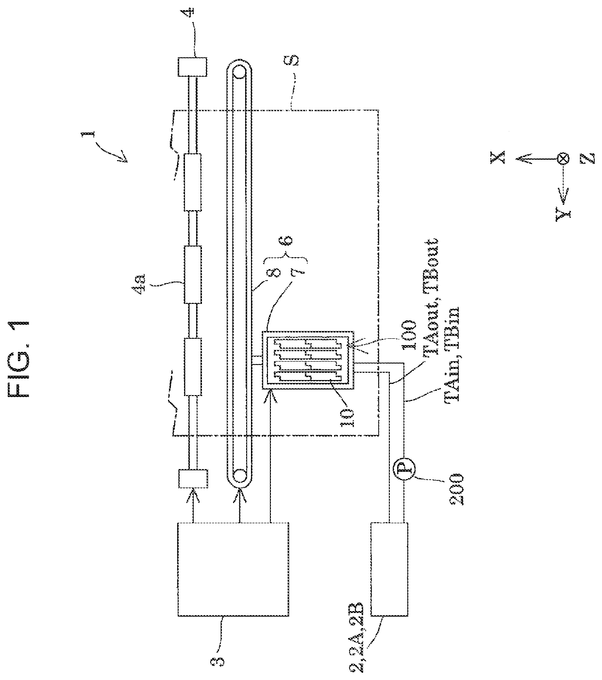
[0035]FIG. 1 is a view illustrating a schematic configuration of an ink jet type recording apparatus 1 which is an example of a “liquid ejecting apparatus” according to Embodiment 1 of the present disclosure.

[0036]As illustrated in FIG. 1, the ink jet type recording apparatus 1 which is an example of the liquid ejecting apparatus is a printing apparatus that performs printing of an image or the like by arranging dots formed on a medium S by ejecting and landing ink, which is a type of liquid, as ink droplets on the medium S, such as a printing paper sheet. As the medium S, any material such as a resin film or cloth can be used in addition to a recording paper sheet.

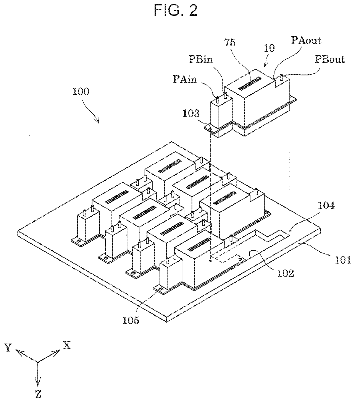
[0037]The ink jet type recording apparatus 1 includes a head module 100 including an ink jet type recording head 10 (hereinafter, also simply referred to as a recording head 10) which is an example of a “liquid ejecting head”, a liquid container 2, a control unit 3 which is a control section, a transport mechanis


PUM


Abstract

There is provided a liquid ejecting head which is long in a first direction and short in a second direction, including: a first introduction section; a second introduction section; a first filter chamber group having a first filter chamber and a second filter chamber; a second filter chamber group having a third filter chamber and a fourth filter chamber; a first supply flow path for supplying the liquid from the first introduction section to the first filter chamber group; and a second supply flow path for supplying the liquid from the second introduction section to the second filter chamber group, in which the first introduction section, the second introduction section, the first filter chamber group, and the second filter chamber group are arranged side by side in this order in the first direction.

Description


Claims


Application Information

Patent Timeline
Owner SEIKO EPSON CORP
Why Eureka
Try Eureka