Imaging system and method

a technology of imaging system and image, applied in the field of situational awareness and automated vehicle control, can solve the problems of difficult extraction, limited spatial resolution of radar and lidar systems, and difficulty in combining information from both types of systems where spatial information mismatch is difficult,

Active Publication Date: 2022-03-17
GM GLOBAL TECH OPERATIONS LLC
View PDF0 Cites 1 Cited by
  • Summary
  • Abstract
  • Description
  • Claims
  • Application Information

AI Technical Summary

Benefits of technology

The invention relates to improving the accuracy with which spectral images are analyzed by combining them into multisensor data sets that can be used for various applications such as environmental monitoring (see also discussing how these techniques help identify specific types of objects). This technology allows us to make better understanding about complex systems without relying on detailed analysis methods like X ray fluorescence imagery.

Problems solved by technology

The technical problem addressed in this patented technology relates to enhancing situational understanding during car navigation operations through image recognition techniques like radar monitoring and cameras. These technologies can help identify objects within an area around a moving body accurately without overlooking important areas with noisy data. This helps improve safety measures and enhances overall driving experience.

Method used


Image

  • Imaging system and method
  • Imaging system and method
  • Imaging system and method

Examples


Embodiment Construction

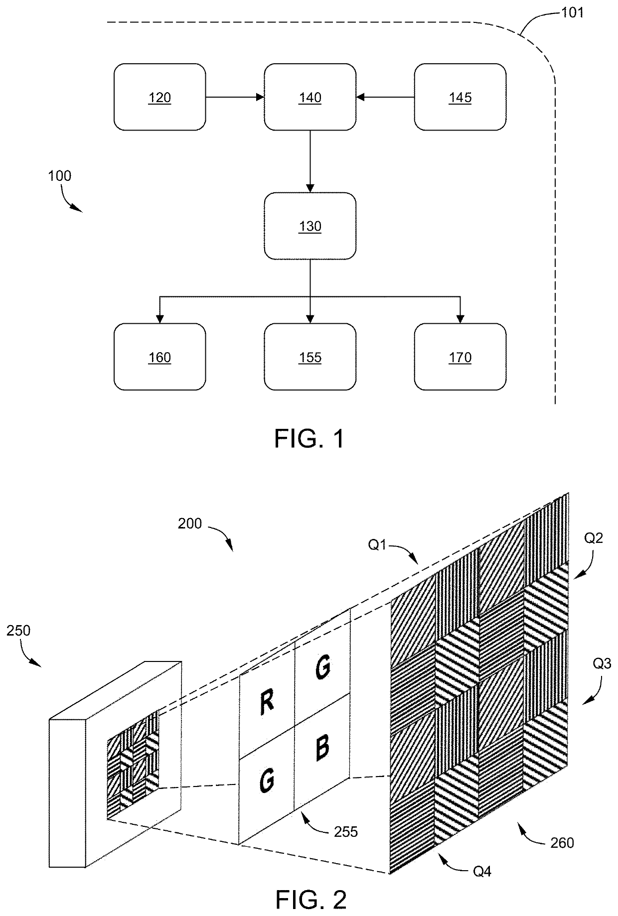
[0031]The following description is merely exemplary in nature and is not intended to limit the present disclosure, its application or uses. Throughout the drawings, corresponding reference numerals indicate like or corresponding parts and features. As used herein, control module, module, control, controller, control unit, electronic control unit, processor and similar terms mean any one or various combinations of one or more of Application Specific Integrated Circuits (ASIC), electronic circuits, central processing units (preferably microprocessors) and associated memory and storage (read only memory (ROM), random access memory (RAM), electrically programmable read only memory (EPROM), hard drive, etc.), graphic processing units, or microcontrollers executing one or more software or firmware programs or routines, combinational logic circuits, input / output circuitry and devices (I / O) and appropriate signal conditioning and buffer circuitry, high speed clock, analog to digital (A / D


PUM


Abstract

A system and method may include capturing a multi-channel polarimetric image and a multi-channel RGB image of a scene by a color polarimetric imaging camera. A multi-channel hyperspectral image may be synthesized from the multi-channel RGB image and concatenated with the multi-channel polarimetric image to create an integrated polarimetric-hyperspectral image. Scene properties within the integrated polarimetric-hyperspectral image may be disentangled.

Description


Claims


Application Information

Patent Timeline
Owner GM GLOBAL TECH OPERATIONS LLC
Why Eureka
Try Eureka