Electrode device for microwave operation

a technology of electrodes and microwaves, applied in the field of electrode devices for microwave operation, can solve the problems of generating heat and energy loss, difficult to apply electrodes at optimal angles to the lesion, and no electrodes usable in laparoscopic microwave, and achieve the effect of easy and reliable control

Inactive Publication Date: 2002-09-17
AZWELL
View PDF8 Cites 86 Cited by
  • Summary
  • Abstract
  • Description
  • Claims
  • Application Information

AI Technical Summary

Benefits of technology

This patented technology allows for easy control over how much force it applies during operation without causing damage to other components within the device's electronic circuitry. It achieves this through dividing up parts of the supporting structure called the elecrosis tube into smaller linkages connected together at different points around its circumference. These linking structures allow some of these linked elements to move freely inside while keeping others fixed in place. By pulling out certain connecting lines behind each section they become less affected than if only pushing forward. Even though many connections may have been added, no sudden curves form throughout the entire assembly due to changes made across the length of the cables themselves.

Problems solved by technology

The technical problem addressed in this patented solution is how to improve upon existing methods for analyzing data from large amounts of data collected over time by making it easier or more efficient than current techniques that require manual input.

Method used


Image

  • Electrode device for microwave operation
  • Electrode device for microwave operation
  • Electrode device for microwave operation

Examples


Embodiment Construction

The present invention is described in further detail below with reference to a typical example. However it is not to intended that the present invention be restricted to the example.

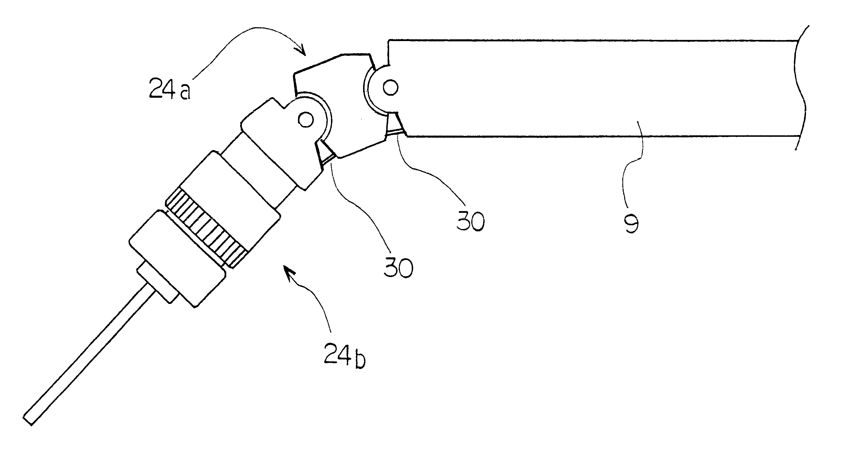
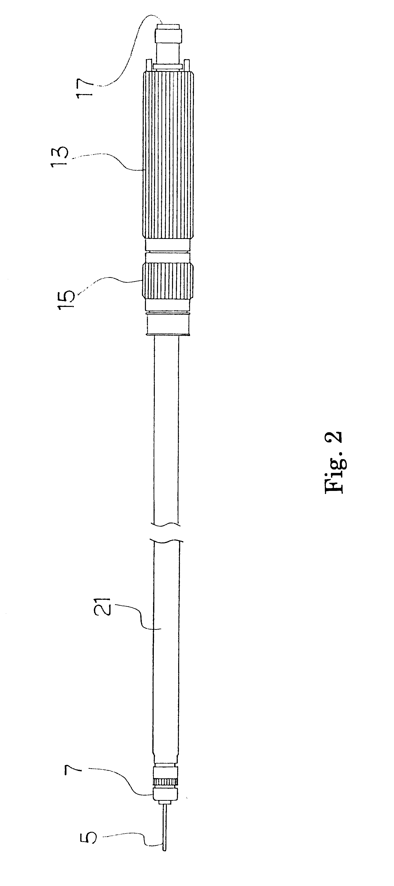
FIG. 1 illustrates a schematic side view of an example of the electrode device for microwave coagulation therapy. While the illustrated example is a so-called monopolar type electrode, a bipolar type electrode may also be used and the shape of the electrode tip may be in a variety of shapes such as ball-like, hook-like, sickle-like or blade-like shapes, since the type or shape of the electrode tip is irrelevant to the present invention. In the figure, 1 indicates an electrode device for microwave coagulation therapy, 5 is a central electrode, and 7 is a tubular ground electrode. 9 is a rigid hollow support shaft made of a metal with a circular cross section, through the interior of which extends a flexible coaxial cable 10 for microwave shown in phantom lines. 11 is a handpiece which is to be held in a hand


PUM


Abstract

An electrode device is for microwave coagulation therapy disclosed in which the direction of its electrode tip can be controlled by operation in its proximal region. The device comprises: a handpiece provided with a rigid hollow support shaft extending toward a distal end, a movable support provided at the distal end of the support shaft and carrying thereon an electrode, a coaxial cable which is connected at its proximal end to a coaxial connector and extending through the support shaft and connected in the movable support to the electrode, wherein: (a) the movable support comprises one or more links each surrounding the coaxial cable and longitudinally connected to the distal end of the support shaft so that the movable support can be bent and stretched in a single plane, and (b) the electrode device comprises a resilient stiff member fixed at one of its end to the deflection side of the most distal one of the links composing the movable support and extending through the support shaft and so connected at its proximal end to a control section of the handpiece that the resilient stiff member can be pulled and pushed back at the proximal end of the handpiece.

Description


Claims


Application Information

Patent Timeline
Owner AZWELL
Why Eureka
Try Eureka