Anode rod depletion indicator
a technology of depletion indicator and anode rod, which is applied in the direction of resistance/reaction/impedence, instruments, measurement devices, etc., can solve the problems of tank failure or corrosion in a relatively short time, steel exposed to moisture and oxygen rusting and corroding, and no way to repair the water heater
- Summary
- Abstract
- Description
- Claims
- Application Information
AI Technical Summary
Benefits of technology
Problems solved by technology
Method used
Image

Examples
first embodiment
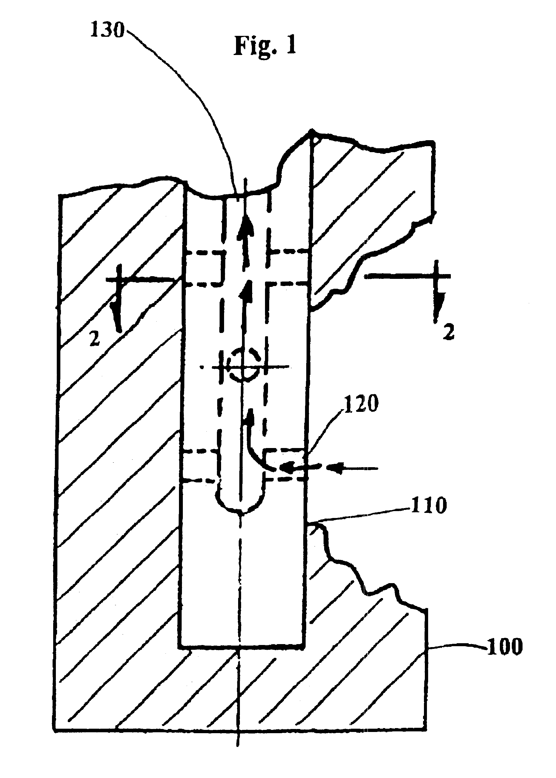
[0084]FIG. 1 illustrates first embodiment of the present invention.
[0085]According to FIG. 1, an anode rod 100 contains a hollow core wire 110 arranged therein. In this particular embodiment, the replacement of the anode is based on the replacement of the anode when the exposure of core wire is 6 inches long from either end of the anode, because several manufacturers of anodes recommend replacement when 6 inches of the core wire becomes exposed at either end of the anode. However, the length of the exposure of the hollow core wire necessary to indicate that the anode rod must be replaced may be any predetermined length according to an individual manufacturer's specification and designs, and the hollow core wire of the present invention may also be of any diameter according to need.
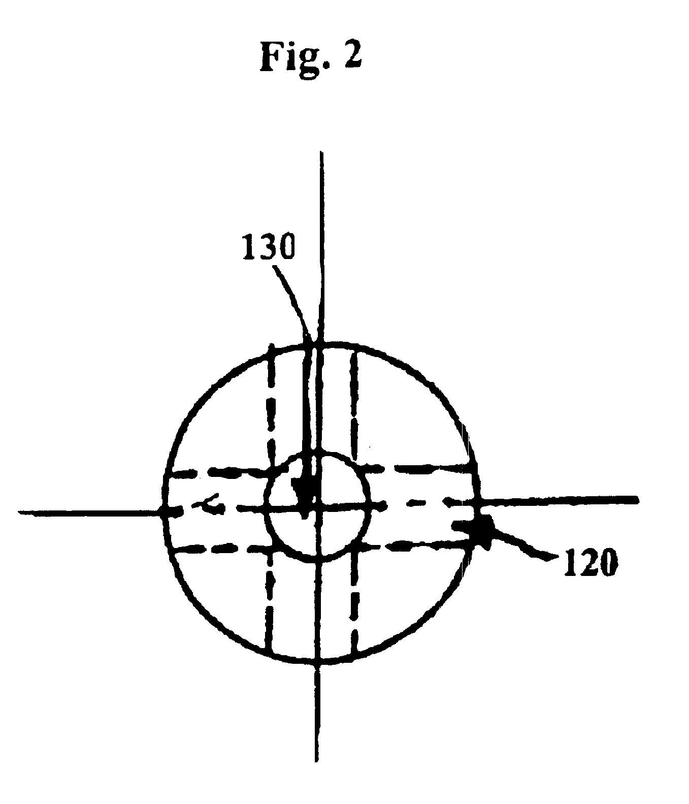
[0086]FIGS. 1 and 2 illustrate a first embodiment of the present invention shown. In this embodiment, the anode 100 has a hollow core wire 110 that has a longitudinal passageway or center hole 130 and substan
second embodiment
[0095]As shown in a second embodiment in FIG. 6, the core wire 610 is fluted, as shown by the passageways 620 shown in the cross-sectional view of the core. These fluted passageways 620 permit fluid to flow through when corrosion has eaten away a sufficient portion of the anode 600 to expose the core wire.
[0096]As shown by the arrows in FIG. 6, fluid in the tank flows up the flutes 620 once the core wire is exposed.
[0097]It is also contemplated that the invention may comprise an anode having the longitudinal and lateral passageways, either without a core wire, or adapted for connection with an electrical source.
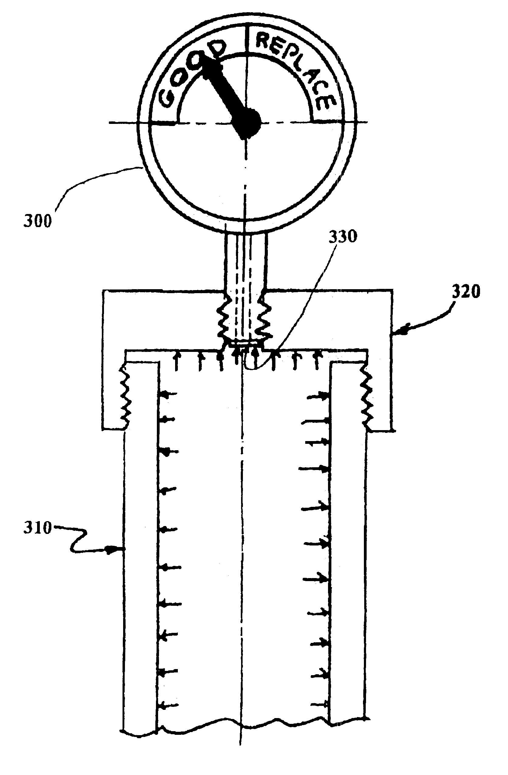
[0098]The fluid then pressurizes and activates a pressure gauge or switch, or the pressurized fluid can push a piston up into a location where it is visible to the homeowner. The homeowner is alerted to the need for replacing the anode rod to prevent corrosion to the internal tank.
[0099]It will be both appreciated and understood by a person of ordinary skill in the art that the
PUM
 Abstract
Description
Claims
Application Information
 - R&D Engineer
- R&D Manager
- IP Professional
- Industry Leading Data Capabilities
- Powerful AI technology
- Patent DNA Extraction
Browse by: Latest US Patents, China's latest patents, Technical Efficacy Thesaurus, Application Domain, Technology Topic.
© 2024 PatSnap. All rights reserved.Legal|Privacy policy|Modern Slavery Act Transparency Statement|Sitemap