Devices, methods and systems for low volume microarray processing
a microarray and microarray technology, applied in the direction of positive displacement liquid engines, laboratory glassware, instruments, etc., can solve the problem that the surface does not provide an exposed analyte sample, and achieve the effect of reducing or preventing the degradation of analyte samples or reagents during processing, reducing or eliminating liquid retention interfaces
- Summary
- Abstract
- Description
- Claims
- Application Information
AI Technical Summary
Benefits of technology
Problems solved by technology
Method used
Image


Examples
example 1
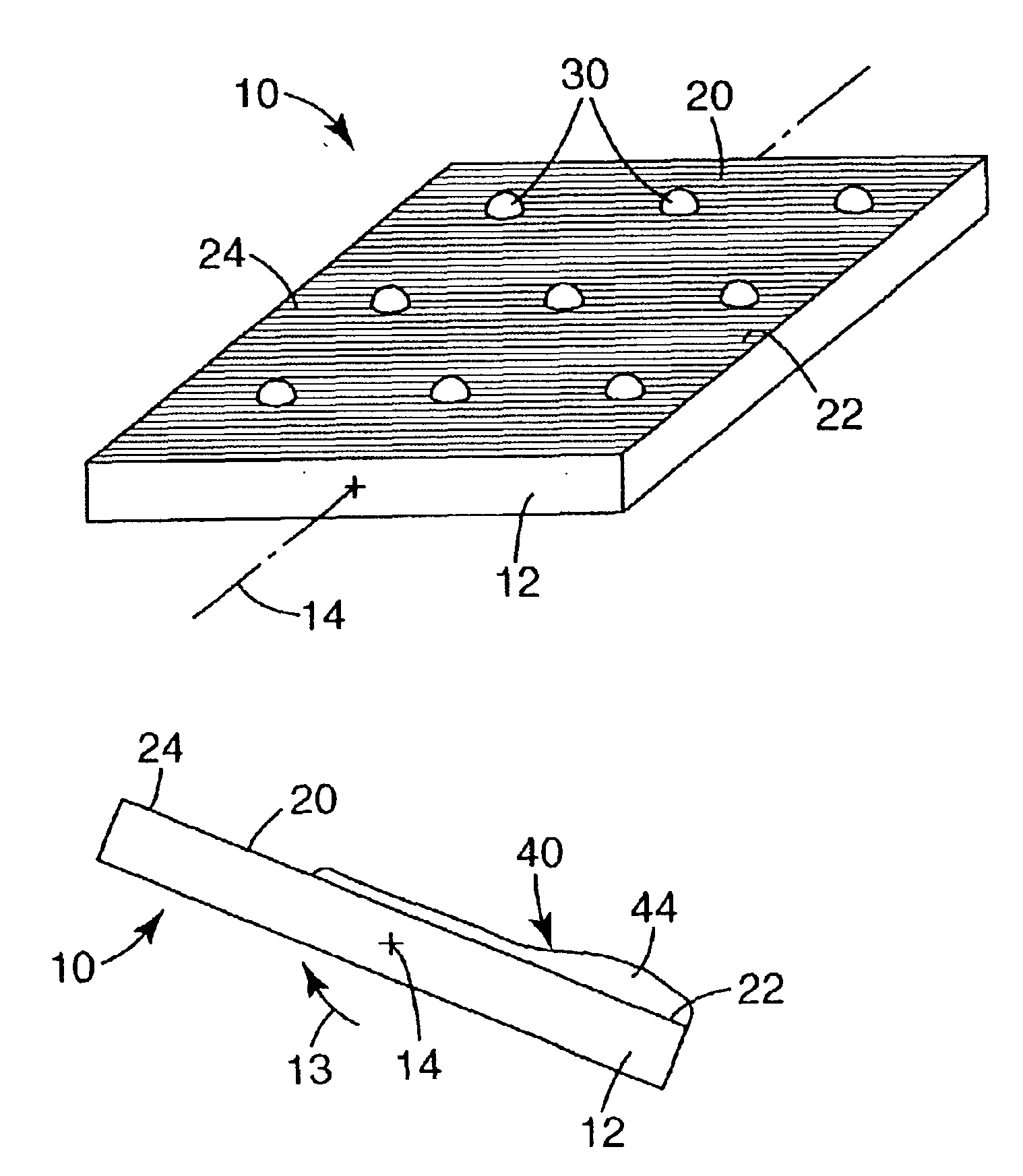
Coated Heat Shrink Film with Undulated Surface
[0094]A sample of polyethylene heat shrink film coated with an azlactone / dimethylacrylamide copolymer was prepared according to International Publication No. WO 99 / 53319, providing a reactant surface having undulated wrinkles. A microarray device having dimensions of 1.8×2.5 cm was adhered to a glass microscope slide. The glass slide with microarray device was placed on a flat, level surface (0 degrees) and 100 microliters of DNA hybridization buffer (3× SSC, 0.3% SDS, 1 mg / ml Yeast tRNA and 1 mg / ml Poly A) was placed on the center of the microarray device. Radial spreading of the liquid was observed, propagating until it reached the outer edges of the microarray device. The sample was then tilted approximately 20 degrees from horizontal. The free liquid above the reactant surface was observed to migrate to the “low” side of the film, accumulating in a linear bead at the edge of the film without draining off. Rotating the microarray
example 2
Nylon Membrane with Porous Fiber Network
[0095]A section of nylon membrane (TAS Membrane, 0.45 micron pore size from BioRobotics, Inc., Cambridge UK) approximately 2×2.5 cm was adhered to a glass microscope slide using double sided adhesive tape to form a reactant surface.
[0096]The glass slide was placed on a flat, level surface (0 degrees) at which time 150 microliters of water containing green food coloring was pipetted onto the center of the membrane. Radial spreading of the solution over the membrane was observed. The sample was gently rotated as described in Example 1. The free liquid not adsorbed into the membrane was observed to accumulate at the edge of the membrane without flowing over the edge. The sample was then rotated to a vertical position, i.e., a 90 degree angle off of horizontal. The solution was retained on the membrane even at that extreme angle.
example 3
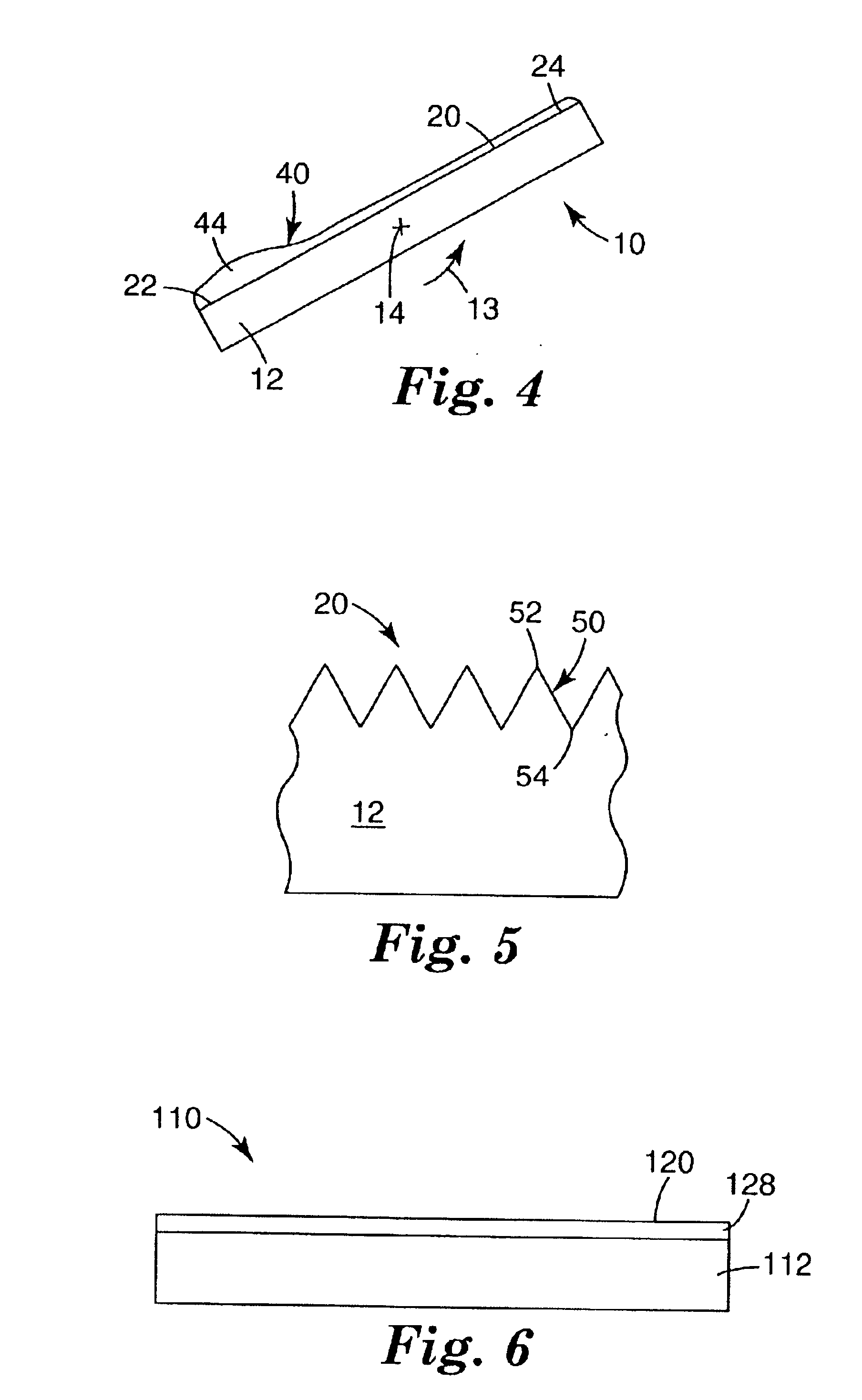
Polymeric Film with V-Channel Structures
[0097]A hydrophilic polypropylene film with a microreplicated structured surface of adjacent linear V-groove channels embossed in the surface was prepared according to U.S. Pat. No. 5,728,466. The embossed polymer surface included open V-grooves having an isosceles triangular cross section with a base angle (the bottom of the “V”) of approximately 135 degrees and a height of approximately 100 micrometers. A section of film approximately 2×2 cm was adhered to a glass microscope slide using double-sided adhesive tape.
[0098]The glass slide was then placed on a flat, level surface at which time 75 microliters of water containing green food coloring (to provide contrast) was pipetted onto the center of the film. The liquid was observed to spread along the V-groove channels until it reached the edge of the film. The sample was tilted approximately 20 degrees. The liquid was observed to migrate along the channels to the “low” side of the film, accumulat
PUM
 Abstract
Description
Claims
Application Information
 - R&D Engineer
- R&D Manager
- IP Professional
- Industry Leading Data Capabilities
- Powerful AI technology
- Patent DNA Extraction
Browse by: Latest US Patents, China's latest patents, Technical Efficacy Thesaurus, Application Domain, Technology Topic.
© 2024 PatSnap. All rights reserved.Legal|Privacy policy|Modern Slavery Act Transparency Statement|Sitemap