Surface acoustic wave arrangement for broadband signal transmission

Active Publication Date: 2006-01-31
SNAPTRACK
View PDF13 Cites 22 Cited by
  • Summary
  • Abstract
  • Description
  • Claims
  • Application Information

AI Technical Summary

Benefits of technology

[0016]The underlying object of the present invention is to provide a SAW arrangement, particularly a broadband SAW bandpass filter, which provides, with a simple design, a particularly good suppression of frequency band within the passband of the arrangement.

Problems solved by technology

This disadvantage can be circumvented through the configuration of an interdigital transducer or converter with a period varying in the transverse direction of the electrode fingers.
Due to strong power level differences between terrestrial and satellite-based signals, undesired interference to the two signal types can occur, under certain circumstances, in the receiver.
This solution has the disadvantage that for long transducers, the angle of the terminal fingers deviates highly from the normal to the wave propagation direction, it is also true that the increase in the fan angle in the corresponding subtrack would lead to an overlapping of the adjacent fingers.
However, this requires a precision which cannot be implemented currently with previously known techniques, such as screen printing.
Another possibility consists of arranging dampening structures or structures for diverting the acoustic wave between the input and output transducer, but this is difficult to implement due to the limited chip length.
A series connection of the subtransducers has the disadvantage that here the impedance of the arrangement is quadrupled.

Method used


Image

  • Surface acoustic wave arrangement for broadband signal transmission
  • Surface acoustic wave arrangement for broadband signal transmission
  • Surface acoustic wave arrangement for broadband signal transmission

Examples


Example

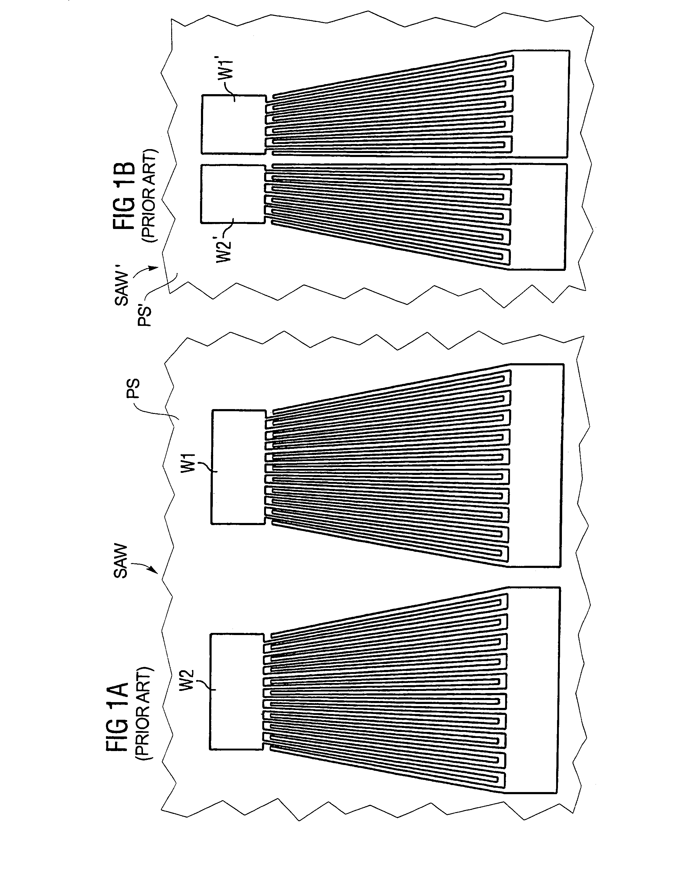
[0045]FIG. 1A shows a known surface acoustic wave arrangement SAW having two interdigital transducers W1 and W2 formed as fan transducers on a portion of a piezoelectric substrate PS. The electrode fingers are arranged on a periodic grid, the period of the grid and, thus, the absolute finger center distances decrease in the selected transverse direction, which is illustrated as in the upward direction. The electrode fingers taper in this direction so that the finger widths measured in wavelengths or rather the finger center distances measured in wavelengths remains constant, but the wavelength decreases with decreasing absolute finger center distances.

[0046]The transducer arrangement shown in FIG. 1A is also known as a dual-focus arrangement, since the electrode fingers of the two transducers W1 and W2 lengthened in the transverse direction converge in each case at a point or focus point.

[0047]In FIG. 1B, another known arrangement SAW′ is a single focused arrangement of two fan transdu


PUM


Abstract

A surface acoustic wave arrangement has at least two interdigital transducers being provided on a piezoelectric substrate along an acoustic path, with at least one of the interdigital transducers being a fan transducer which is divided in a transverse direction into edge tracks and a center track. The acoustic wave excited in the edge tracks can be radiated either bidirectionally or unidirectionally in a predominant direction. On the other hand, the center track is formed so that the unidirectional radiation of the wave takes place in a direction opposite the predominant direction. In this manner, the signal transmission is suppressed in the frequency range corresponding to the finger period in the center track within the passband range of the transfer function. The obtained notch in the transfer function is used, for example, in receivers of terrestrial and satellite-based signals for suppressing the terrestrial signals in the satellite path of the receiver.

Description


Claims


Application Information

Patent Timeline
Owner SNAPTRACK
Why Eureka
Try Eureka