Arithmetic circuit

Active Publication Date: 2006-03-07
LAPIS SEMICON CO LTD
View PDF8 Cites 3 Cited by
  • Summary
  • Abstract
  • Description
  • Claims
  • Application Information

AI Technical Summary

Benefits of technology

[0013]An arithmetic circuit of the present invention comprises arithmetic means for performing an arithmetic operation of a predetermined bit width in accordance with an arithmetic operation instruction, holding means for holding status information about the result of the arithmetic operation by the arithmetic means, logic means for performing logic operation processing of ORing or ANDing of the

Problems solved by technology

The conventional arithmetic circuit, however, has the following problems.
Therefore, a problem arises in that there is a need to execute add processing with a view toward obtaining the proper value of the Z flag, and the number of program-steps increases and a processing time becomes long.
Similarly, a pro

Method used


Image

  • Arithmetic circuit
  • Arithmetic circuit
  • Arithmetic circuit

Examples


first embodiment

(First Embodiment)

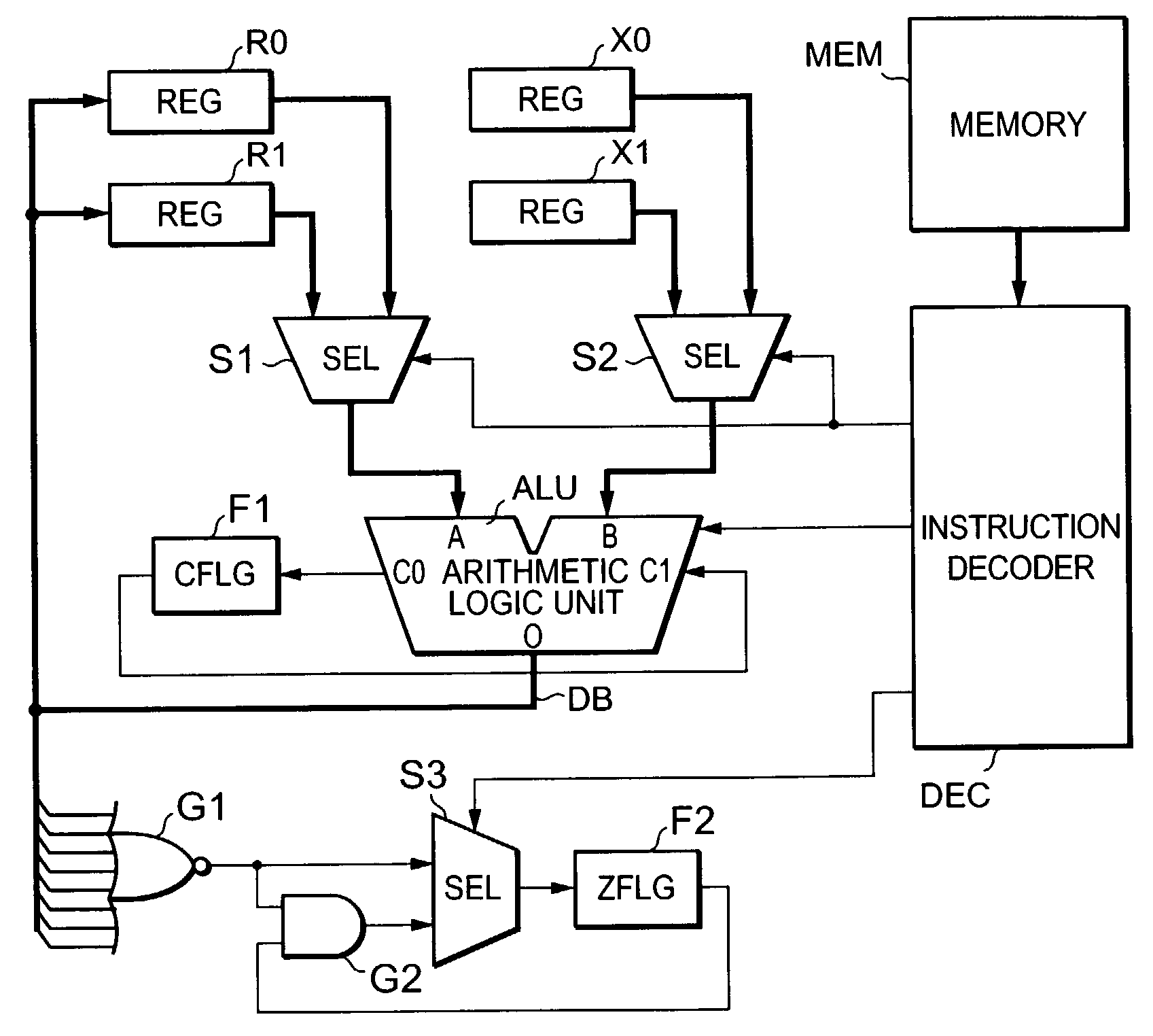
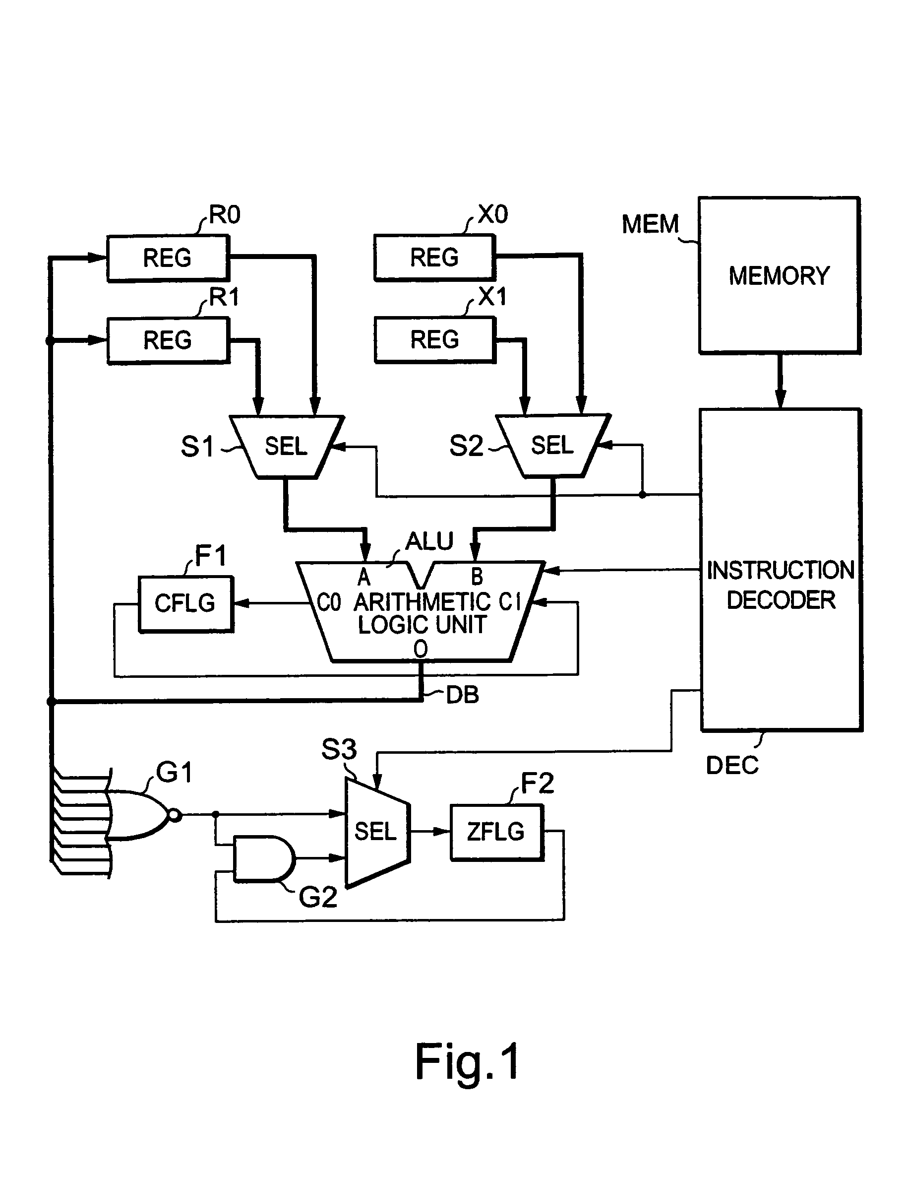
[0021]FIG. 1 is a block diagram of an arithmetic circuit showing a first embodiment of the present invention.

[0022]The arithmetic circuit is one wherein in a microprocessor or the like, an 8-bit adder-subtractor is used to perform addition and subtraction of 16-bit integers. The arithmetic circuit has registers (REG) R0 and R1 each of which sets an augend (or minuend) and stores the result of addition (or subtraction) after its arithmetical operation, and registers X0 and X1 for respectively setting an addend (or subtrahend). Any of the registers R0, R1, X0 and X1 has an 8-bit data width. Lower 8 bits are set to the registers R0 and X0, and upper 8 bit are set to the registers R1 and X1, respectively.

[0023]The values of the 8 bits set to the registers R0 and R1 are supplied to a 8-bit input terminal A of a computing circuit or arithmetic logic unit (e.g., adder-subtractor) ALU through a selector S1, and the values of the 8 bits set to the registers X0 and fX1 are supp

second embodiment

(Second Embodiment)

[0043]FIG. 3 is a block diagram of an arithmetic circuit showing a second embodiment of the present invention. Elements of structure common to the elements shown in FIG. 1 are respectively identified by common reference numerals.

[0044]The arithmetic circuit is one wherein the arithmetic circuit shown in FIG. 1 is provided with a computing circuit (e.g., shifter) SFT, selectors S4, S5 and S6, and a logic circuit (e.g., a two-input logical sum (hereinafter called “OR”) gate) G3. The shifter SFT left-shifts data of 8 bits selected by a selector S1 in one-bit units. Namely, when an unillustrated control signal is supplied from an instruction decoder DEC to the shifter SFT, the shifter SFT shifts 8-bit data supplied to its input terminal I to the left one bit by one bit. At this time, the most significant bit is outputted from a carry output terminal CO of the shifter SFT as a carry signal. Further, “0” is set as the least significant bit, and the 8-bit data corresponding


PUM


Abstract

An arithmetic circuit includes an arithmetic circuit performing an arithmetic operation of a predetermined bit width in accordance with an arithmetic instruction, a holding circuit storing status information about the arithmetic operation by the arithmetic circuit and a logic circuit having a function of a logic operation. The logic circuit receives the status information stored in the holding circuit and the status information about a present result of arithmetic operation. The arithmetic circuit further includes a selector for selecting either the status information about the present result of arithmetic operation or a signal outputted form the logic circuit in accordance with a control signal based on the arithmetic instruction. The selector supplies the selected signal to the holding circuit.

Description


Claims


Application Information

Patent Timeline
Owner LAPIS SEMICON CO LTD
Why Eureka
Try Eureka