Torque reaction control jig

Inactive Publication Date: 2006-03-21
HONDA MOTOR CO LTD
View PDF9 Cites 12 Cited by
  • Summary
  • Abstract
  • Description
  • Claims
  • Application Information

AI Technical Summary

Benefits of technology

[0008]In accordance with the present invention, a torque reaction control jig is adapted to transfer reaction torque from a drive member to a wheel upon tightening of a spindle nut onto an axle. The jig includes a jig body, an alignment member, and a barrier member. The jig body is secured to the drive member in a non-rotatable fashion. The alignment member includ

Problems solved by technology

There exist situations wherein such control bars cannot be implemented due to environmental or space considerations, such as when tightening a spindle nut on a stub axle/wheel assembly during assembly of a vehicle.
In this situation, the operator may improperly apply the torque reaction control bar, damaging the part and potentially injuring the operator.
Accordingly, conventional torque reaction control bars have gener

Method used


Image

  • Torque reaction control jig
  • Torque reaction control jig
  • Torque reaction control jig

Examples


Embodiment Construction

[0017]In the following description, the various sides and surfaces of the alignment jig of the present invention are described as they are presented in the drawings. Accordingly, the use of the directional references (i.e., upper, lower, lateral side, etc.,) is only to be construed as they relate to the orientation of the jig in the drawings. Insofar as the jig is capable of use in various orientations, these directional references are not to be construed in a limiting fashion.

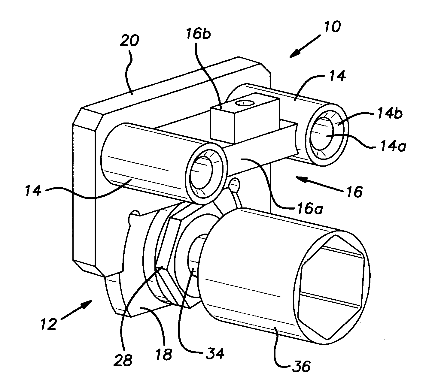
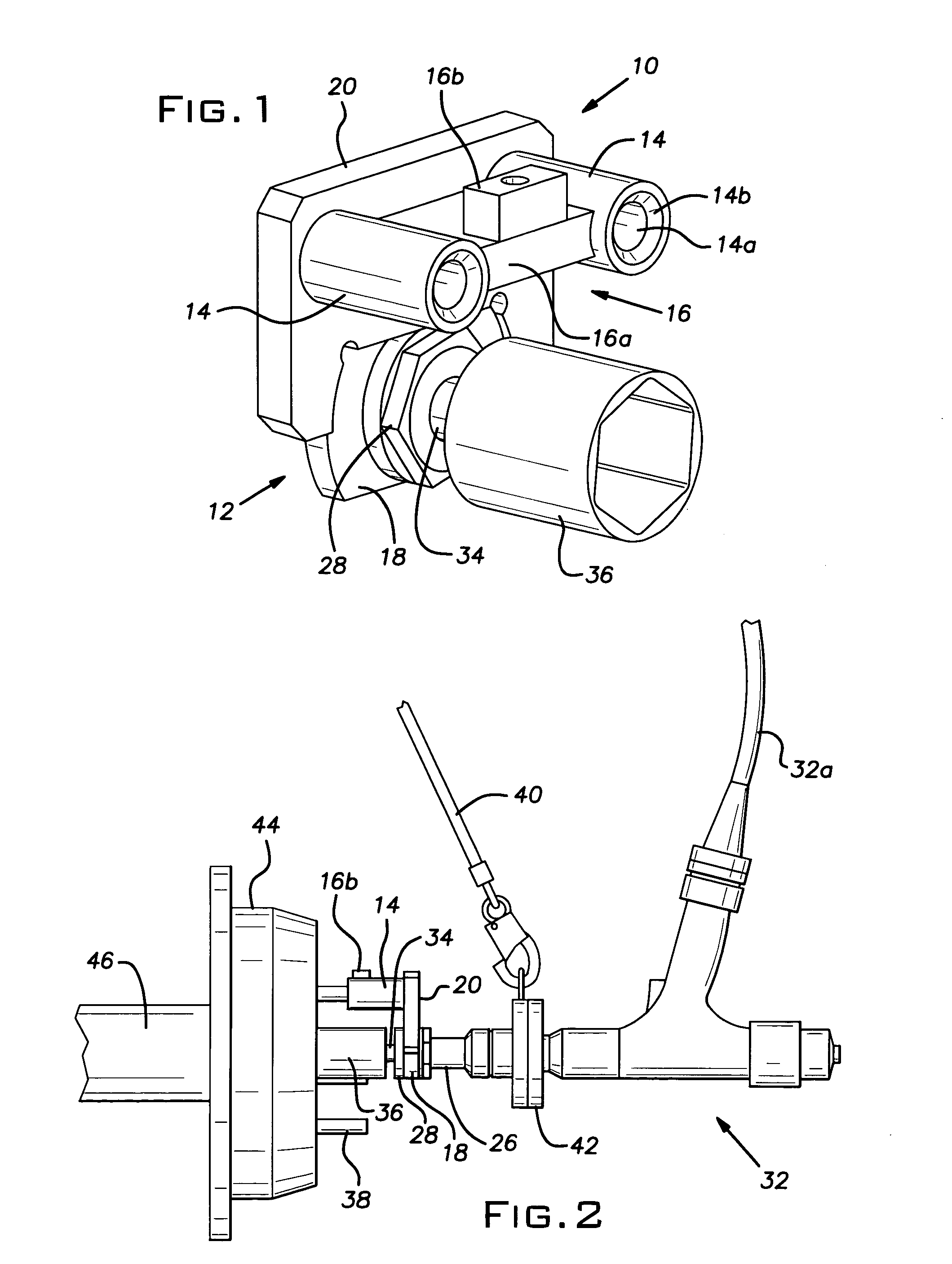
[0018]With reference to FIGS. 1–3, the torque reaction control jig 10 of the present invention includes a jig body 12, a pair of wheel stud receptacles or nests 14, and a barrier member 16. In the preferred and illustrated embodiment, the jig body 12 includes an adaptor body 18 that is affixed to an alignment body 20.

[0019]The adaptor body 18 has a generally rectangular peripheral shape, albeit with curved or arcuate lateral sides, and is partially received within a similarly shaped, downwardly facing recess form


PUM


Abstract

A torque reaction control jig that transfers reaction torque from a drive member to a wheel upon tightening of a spindle nut onto a vehicle axle. The jig includes a jig body, an alignment member, and a barrier member. The jig body is secured to the drive member in a non-rotatable fashion. The alignment member includes a pair of stud nests that are each adapted to slidingly receive a wheel stud. The barrier member is secured to the jig body in a location such that the barrier member will engage the wheel stud should the jig be misaligned with the wheel. Engagement between the barrier member and the wheel prevents further tightening of the spindle nut onto the axle until the jig is properly aligned with the wheel.

Description


Claims


Application Information

Patent Timeline
Owner HONDA MOTOR CO LTD
Why Eureka
Try Eureka