Bearing for wheel suspensions in a motor vehicle

Inactive Publication Date: 2006-05-09
ZF BOGE ELASTMETALL
View PDF9 Cites 3 Cited by
  • Summary
  • Abstract
  • Description
  • Claims
  • Application Information

AI Technical Summary

Benefits of technology

[0004]Based on this, the object of the present invention is to provide a bearing in which a rubber buffer is arranged in a pot-shaped metallic housing in such a way that when the bearing i

Problems solved by technology

The drawback of these is that the rubber buffer is pretensioned between two flat surfaces, so that thi

Method used


Image

  • Bearing for wheel suspensions in a motor vehicle
  • Bearing for wheel suspensions in a motor vehicle
  • Bearing for wheel suspensions in a motor vehicle

Examples


Embodiment Construction

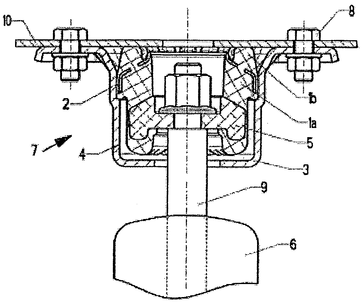
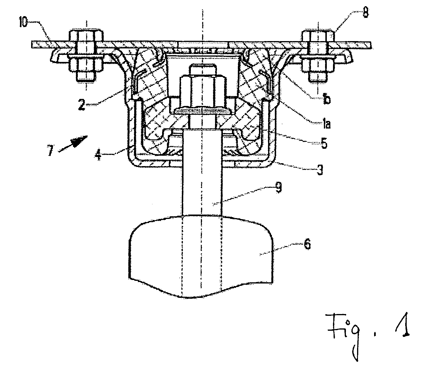
[0016]Referring to the drawings in particular, the bearing 7 shown in FIG. 1 is connected via the screw connections 8 with the vehicle body 10 (e.g. the chassis) of a motor vehicle, while the piston rod 9 of the piston-and-cylinder unit 6 is received and fixed in the bearing 7.

[0017]The rubber buffer 1 is first accommodated in the pot-shaped housing 3 of the bearing 7, and the upper area is supported as the tensioning buffer (a tensioning buffer portion) 1b of the rubber buffer 1 at the inner wall 4 of the housing 3 via the reinforcing part 2. The inner part 5 is embedded in the damping buffer (damping buffer portion) 1a of the rubber buffer 1 in the lower part of the rubber buffer1, and permits the fixation of the piston rod 9 at the inner part 5 due to the corresponding through holes of both the rubber buffer 1, of the inner part 5 and of the housing 3.

[0018]Due to the inner part 5 being embedded in the rubber buffer 1, the piston-and-cylinder unit 6 or the piston rod 9 is enabled to


PUM


Abstract

A bearing for wheel suspensions in a motor vehicle includes a metallic housing with a pot-shaped vertical section, a rubber buffer arranged in the housing, and an inner part. The inner part can be connected to a piston-and-cylinder unit and is fixed in the rubber buffer. A reinforcing part, which is supported axially and/or radially at the inner wall of the housing, is arranged in the rubber buffer.

Description


Claims


Application Information

Patent Timeline
Owner ZF BOGE ELASTMETALL
Why Eureka
Try Eureka