Current collector for use in a fuel cell

a current collector and fuel cell technology, applied in the direction of fuel cells, cell components, electrochemical generators, etc., can solve the problems of reducing contact resistance, reducing the widespread commercial acceptance and perceived usefulness of fuel cells, and reducing the acceptance of fuel cells. , to achieve the effect of hydrating the ion exchange membrane, facilitating heat dissipation, and reducing the difficulty of contact resistan

Active Publication Date: 2006-06-06
EMERGENT POWER
View PDF51 Cites 23 Cited by
  • Summary
  • Abstract
  • Description
  • Claims
  • Application Information

AI Technical Summary

Benefits of technology

The technical effect described this patented technology allows for efficient production of electricity from fuels such as alcohols or gases through use of a special type material called anion-exchange membranes (AEMs). These materials have specific properties allowing them to absorb and release moisture while also being able to maintain their shape even if they expand due to changes in temperature. This results in more stable power generation over time compared to traditional methods like burning fossil fuels.

Problems solved by technology

The technical problem addressed in this patents relates to reducing the amount of contact resistances within each component used during manufacturing processes while maintaining good conductivity properties throughout the entirety of the components themselves. Additionally, it addresses how different types of materials affect the behavior of certain diffusive elements such as platens located near the interface between two elec troxide plasmonics.

Method used


Image

  • Current collector for use in a fuel cell
  • Current collector for use in a fuel cell
  • Current collector for use in a fuel cell

Examples


Embodiment Construction

[0030]This disclosure of the invention is submitted in furtherance of the constitutional purposes of the U.S. Patent Laws “to promote the progress of science and useful arts” (Article 1, Section 8).

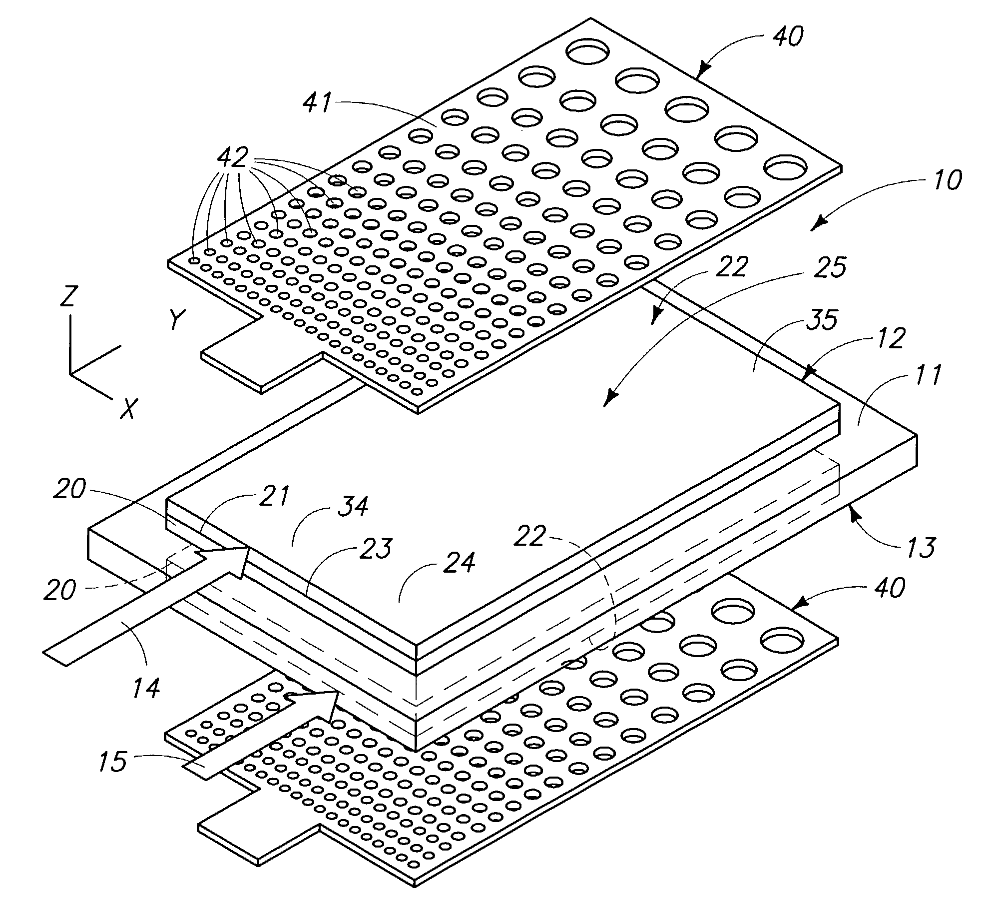
[0031]FIG. 1 is a greatly enlarged, perspective, exploded view of a membrane electrode diffusion layer assembly 10 and associated current collectors which employs the teachings of the present invention. The membrane electrode diffusion layer assembly (MEDLA) is received within, or made integral with, an ion exchange membrane fuel cell module such as what is depicted in FIGS. 11 and / or 12, the features of which will be discussed in greater detail hereinafter. The current collectors employed with the MEDLA will also be discussed in later paragraphs. For purposes of the present discussion, however, the MEDLA 10, as will be disclosed below, is useful in fuel cells which operate at temperatures of less than about 300° C. Consequently, this invention is not useful in solid oxide fuel cell design


PUM


Abstract

A current collector for use in a fuel cell is described and wherein the fuel cell includes an ion exchange membrane having opposite anode and cathode sides, and a current collector is disposed in ohmic electrical contact with each of the anode and cathode sides, and wherein at least one of the current collectors has a surface area which provides substantially effective operational hydration for the ion exchange membrane.

Description


Claims


Application Information

Patent Timeline
Owner EMERGENT POWER
Why Eureka
Try Eureka