Product transfer assembly for a vending machine

a product transfer and vending machine technology, applied in the field of vending machines, can solve the problems that other products are not likely to capture the attention of consumers for a long time, and achieve the effects of reducing dislocation, enhancing excitement value, and improving control of downward travel of product items

Inactive Publication Date: 2010-08-03
CHANG KIL JAE
View PDF12 Cites 14 Cited by
  • Summary
  • Abstract
  • Description
  • Claims
  • Application Information

AI Technical Summary

Benefits of technology

This patented design improves the control of products during their movement on a conveyor system. It introduces a modification made to the zigzag shape of the conveyor system to improve its effectiveness with regards to controlling downward travel of objects. Additionally, it suggests adding spiral shaping to the paths of travel to enhance the excitement level associated with the conveyed object. Overall, this design helps to ensure efficient operation and encourages customers to repeatedly use the vender's machines.

Problems solved by technology

The technical problem addressed in this patent is how to improve the functionality of vending machines while also providing entertainment values to customers who want to purchase them.

Method used


Image

  • Product transfer assembly for a vending machine
  • Product transfer assembly for a vending machine
  • Product transfer assembly for a vending machine

Examples


Embodiment Construction

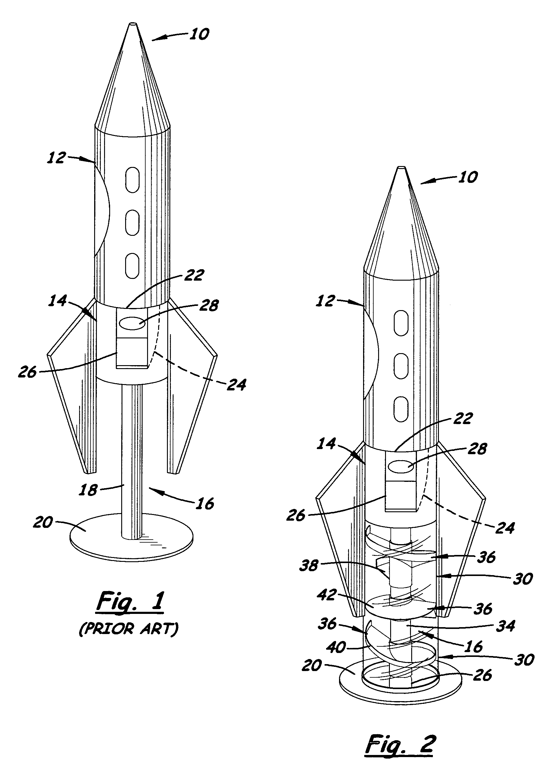
[0017]Referring to the drawings and particularly to FIG. 1, there is generally illustrated an exemplary embodiment of a prior art vending machine 10 in which the present invention may be advantageously incorporated as seen in FIG. 2. The prior art vending machine 10 basically includes a reservoir 12 for holding items of the product in a bulk form and a housing 14 supporting the reservoir 12 and, in turn, mounted on a stand 16 having an elongated tubular support member 18 and a flat base 20 fixedly attached to a lower end of the tubular support member 18 so as to maintain it in an upright orientation. The prior art vending machine 10 also includes a coin-actuated dispensing mechanism 22 mounted to and within the housing 14 and thus disposed below and in communication with the reservoir 12, and a discharge chute structure 24 mounted inside the housing 14 which communicates with the dispensing mechanism 22 and routes one or more product items to an exterior dispensing location 26 on the h


PUM

PropertyMeasurementUnit
Shapeaaaaaaaaaa
Areaaaaaaaaaaa
Distanceaaaaaaaaaa

Abstract

A product transfer assembly includes separate transfer segments mounted in a vending machine such that they are disposed in spaced relationship above one another. Each transfer segment has a ramp of helical shape with an exit end and an entrance end spaced above the exit end such that the ramps of the transfer segments together define a path of travel taken by a product item down and in contact with the ramps which includes spaced apart portions helical in shape and reversing the direction of travel of the product item, relative to a generally vertical reference axis, going from one portion to the next portion of the path. Entrance and exit ends of each ramp are angularly displaced from corresponding ends of an adjacent ramp such that the object free-falls out of contact with any ramp between the exit and entrances ends of adjacent ramps.

Description


Claims


Application Information

Patent Timeline
Owner CHANG KIL JAE
Why Eureka
Try Eureka