Automatic transmission pump-priming device

a technology of automatic transmission and pump, which is applied in the direction of fluid couplings, positive displacement liquid engines, liquid fuel engines, etc., can solve the problems of engine stall on transmission engagement, slow torque converter charge at engine idle, and pump nois

Inactive Publication Date: 2011-02-01
SONNAX INDS
View PDF6 Cites 4 Cited by
  • Summary
  • Abstract
  • Description
  • Claims
  • Application Information

AI Technical Summary

Benefits of technology

The present pump priming device helps to direct some of the regulated exhaust fluid away from the pump when it's being used during high-speed operation. It also improves the efficiency of the pump by reducing its work load.

Problems solved by technology

This patent describes a problem with current designs used in automatic transmissions for land vehicles due to excessive pressure caused by the use of negative displacement pumps. These pumps have different pressures depending on their rotational speed and hydraulic pressure. To solve this issue, there is a pressure regulator valve called Piston and Spring that helps maintain a steady pressure in the hydraulic system when the ATF flows through. However, if the hydraulic pressure becomes too low, the valve will stop working properly, causing issues like poor fuel economy and reduced performance.

Method used


Image

  • Automatic transmission pump-priming device
  • Automatic transmission pump-priming device
  • Automatic transmission pump-priming device

Examples


Embodiment Construction

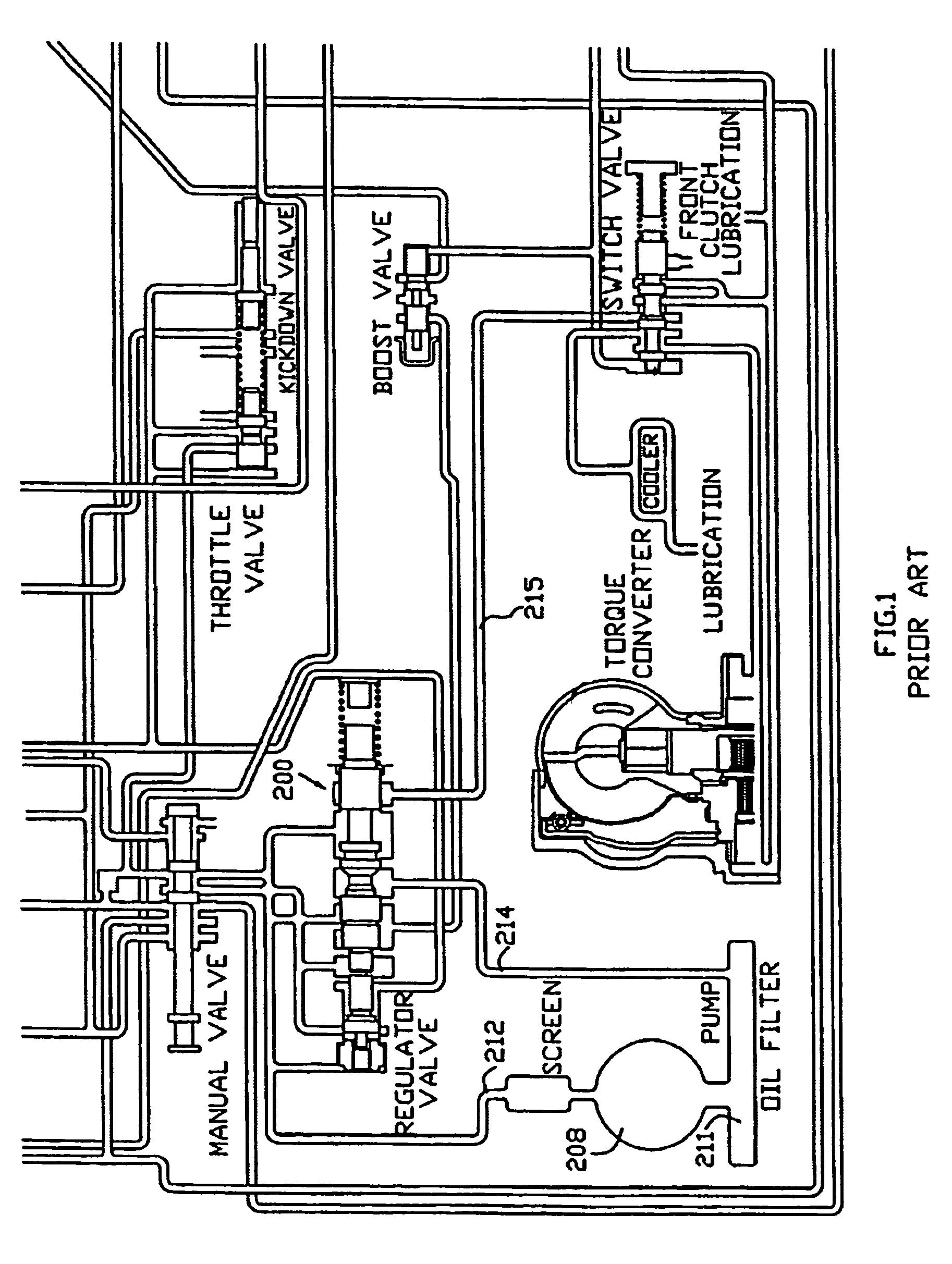
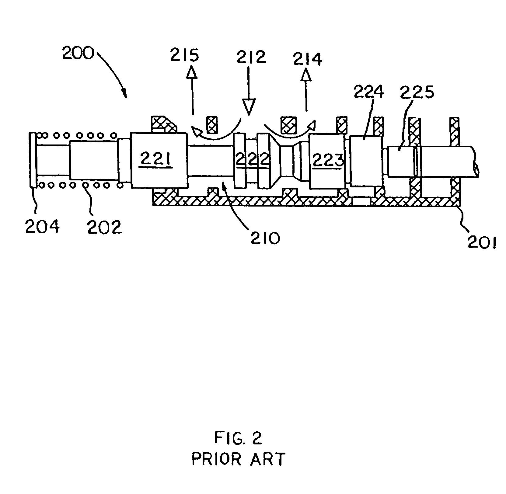
[0021]Prior to describing the present invention in detail it may be beneficial to briefly review the function of the pressure regulator valve and the ATF pump within the hydraulic system of the CHRYSLER transmissions. Referring to FIG. 1 there is shown a partial schematic of the hydraulic system of the aforementioned Chrysler transmissions wherein a pressure regulator valve, indicated generally at 200, is illustrated. The pressure regulator valve 200 is located within the valve body 201 (FIG. 2) of the transmission and regulates line pressure in relation to vehicle operating conditions. In operation ATF at line pressure (i.e. 160-270 psi) from the hydraulic pump 208 enters the pressure regulator valve 200 via pump output circuit 212. The pressure regulator valve 200 routes ATF into both the converter charge circuit 215 and the sump return circuit 214 as shown in FIG. 1 depending on engine speed and operating conditions.

[0022]As seen more clearly in FIG. 2, the pressure regulator valve


PUM


Abstract

A pump-priming device configured to fit within the pump inlet circuit formed in the valve body of an automatic transmission is disclosed. The present pump priming device comprises a fluid-conducting structure having a fluid inlet and a fluid outlet, which is fabricated from sheet metal or flexible tubing and is designed to be installed within the original equipment manufacture valve body as a drop-in-place component. The present pump priming device diverts the flow of automatic transmission fluid (i.e. regulator exhaust fluid) released by the pressure regulator valve, which under normal operating conditions would flow from the pressure regulator valve back to the sump, and to redirect such flow of regulator exhaust fluid back to the pump inlet. Such redirection of regulator exhaust fluid pressurizes the pump inlet circuit and raises the output of the pump to provide adequate transmission fluid flow within the hydraulic system at low engine speeds.

Description


Claims


Application Information

Patent Timeline
Owner SONNAX INDS
Why Eureka
Try Eureka