Multi-sectional bobbin for high voltage inductor or transformer

a transformer and multi-sectional technology, applied in the direction of transformer/inductance details, coils, electrical equipment, etc., can solve the problems of insufficient insulation layer of transformer (or inductor) wire, inability to resist electrical breakdown, and tend to interfere with mass production, so as to prevent wire slippage

Inactive Publication Date: 2011-08-02
TESSERA INC
View PDF6 Cites 9 Cited by
  • Summary
  • Abstract
  • Description
  • Claims
  • Application Information

AI Technical Summary

Benefits of technology

In this invention there are two ways for preventing damage caused by unwanted movement during electrical testing: The technical effect of these structures on the conductor's pathway inside the device is improved stability when it goes through different stages of operation without getting stuck between them due to factors like gravity or friction.

Problems solved by technology

The technical problem addressed by this patented technology relating to improving the performance of magnetic devices used for power transmission has been finding ways to prevent damage caused by electricity during use without adding extra components beyond what was previously necessary.

Method used


Image

  • Multi-sectional bobbin for high voltage inductor or transformer
  • Multi-sectional bobbin for high voltage inductor or transformer
  • Multi-sectional bobbin for high voltage inductor or transformer

Examples


Embodiment Construction

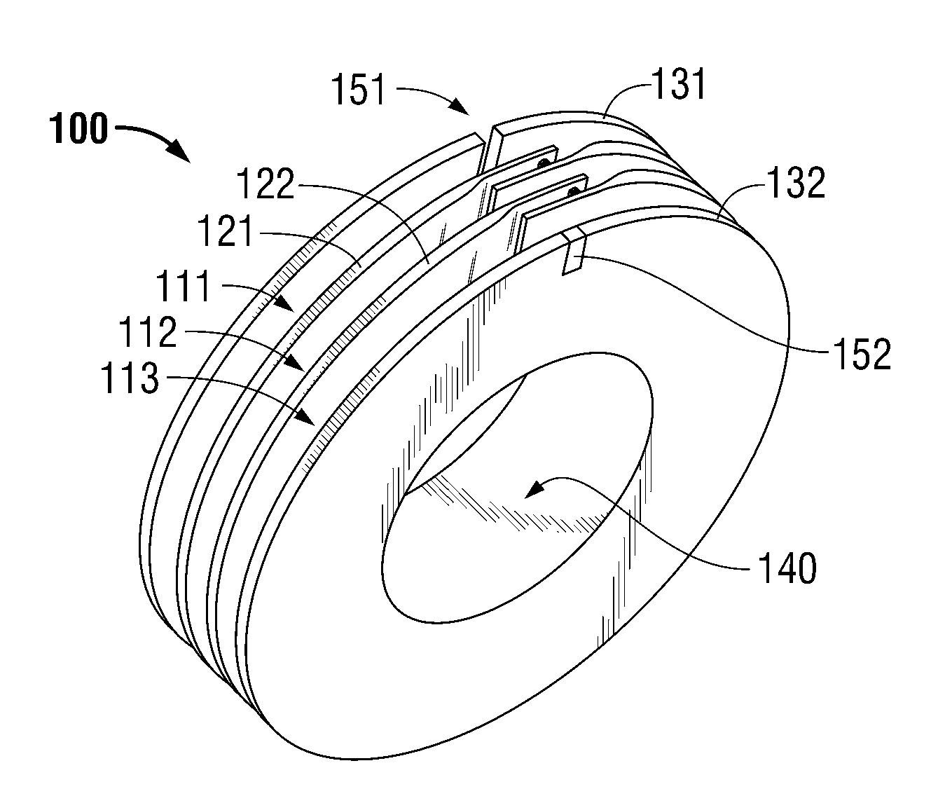
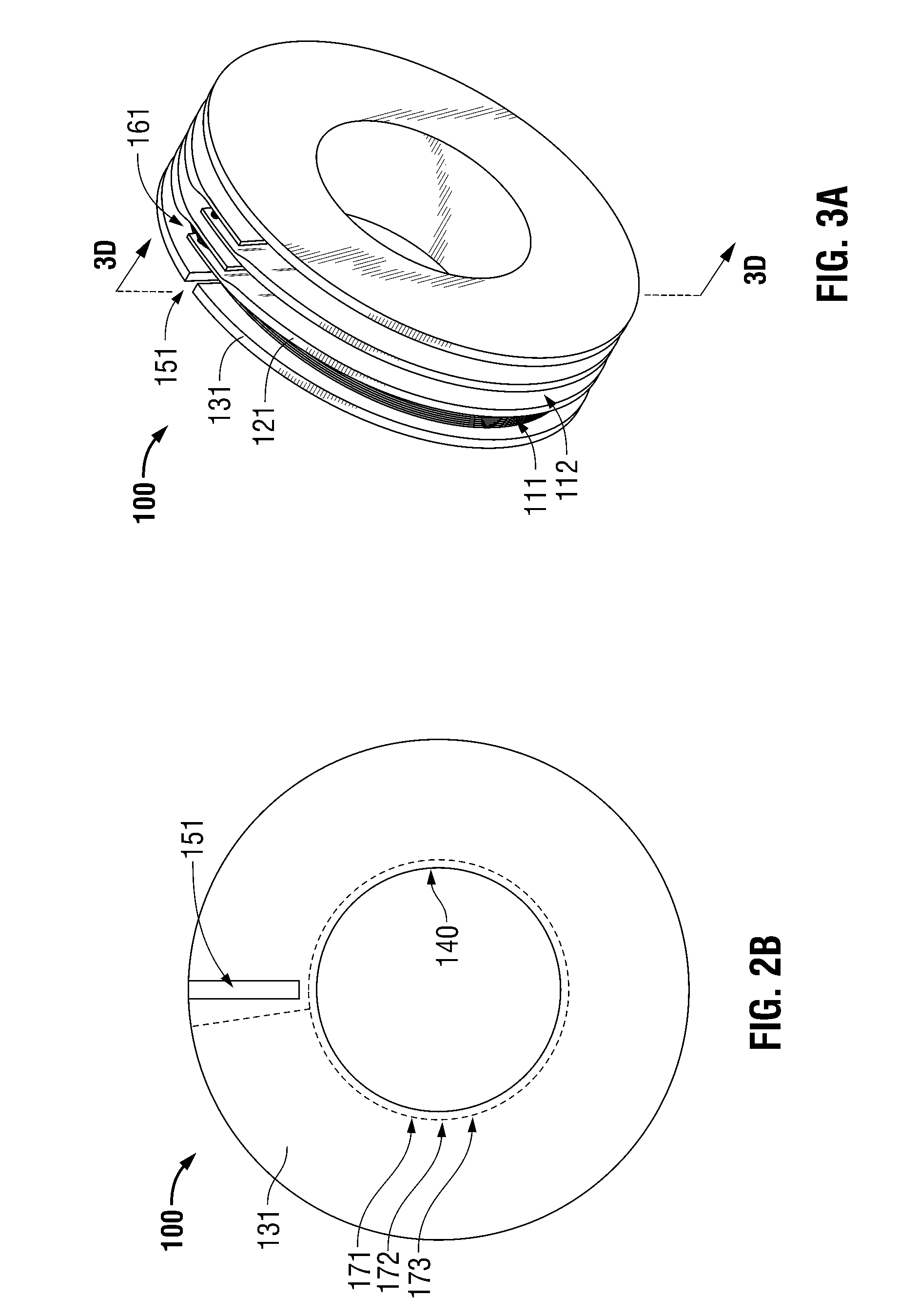
[0026]Inductors, coils and transformers are widely used in electric designs and systems. Typically, wire or some other conductor is wound around a spindle or winding form, hereinafter referred to as a “bobbin” in order to impart desired structure to the windings and, often, to facilitate alignment of such windings with a core. Persons of ordinary skill in the art will appreciate a wide variety of bobbin configurations, geometries, material selections, conductors, core configurations, etc. and this description does not attempt to inventory the substantial diversity of such variations. Instead, in the interests of conciseness and specificity with respect to certain inventive aspects, the present description focuses on exemplary embodiments in which a circular multi-sectional bobbin is wound (or windable) with wire in configurations typical (or at least illustrative) of coils employed in compact, small-form factor, high-voltage transformers. Based on that description context, persons of o


PUM


Abstract

Improved multi-sectional bobbin designs described herein define a channel suitable to accommodate a portion of the wire that transits from prior winding section to the next, wherein opposing walls of the channel so defined separate the transiting portion of the wire from both prior and next winding sections through a substantial entirety of the wires descent from an upper winding layer in the prior section to a lower winding layer in the next.

Description


Claims


Application Information

Patent Timeline
Owner TESSERA INC
Why Eureka
Try Eureka