Security threat detection system

a technology of threat detection and detection system, applied in the field of security threat detection system, can solve the problems of low power consumption, low vulnerability to defeat, high probability of detection, etc., and achieve the effect of low false alarm rate, low cost and effective detection of motion

Active Publication Date: 2012-11-06
WONG THOMAS K
View PDF11 Cites 75 Cited by
  • Summary
  • Abstract
  • Description
  • Claims
  • Application Information

AI Technical Summary

Benefits of technology

This new technology solves issues by providing a way to accurately identify small movements without being detected too frequently (false alarms). It'll be affordable at lower costs while still giving accurate results when used alone during dark conditions like snowfall. Its ability to monitor movement across different weather makes them suitable for use on various surfaces such as buildings, roadsides, etc., regardless of whether they have been previously covered up or damaged due to environmental factors that could trigger dangerous events.

Problems solved by technology

Technological Problem: Existing technology uses multiple different techniques like optical interference scanning and laser beam based methods to achieve accurate intruder detection without being expensive or bulky equipment. Additionally, existing solutions only work within specific ranges of temperature and proximity, making them unreliable when applied outside extreme weather conditions.

Method used


Image

  • Security threat detection system
  • Security threat detection system
  • Security threat detection system

Examples


Embodiment Construction

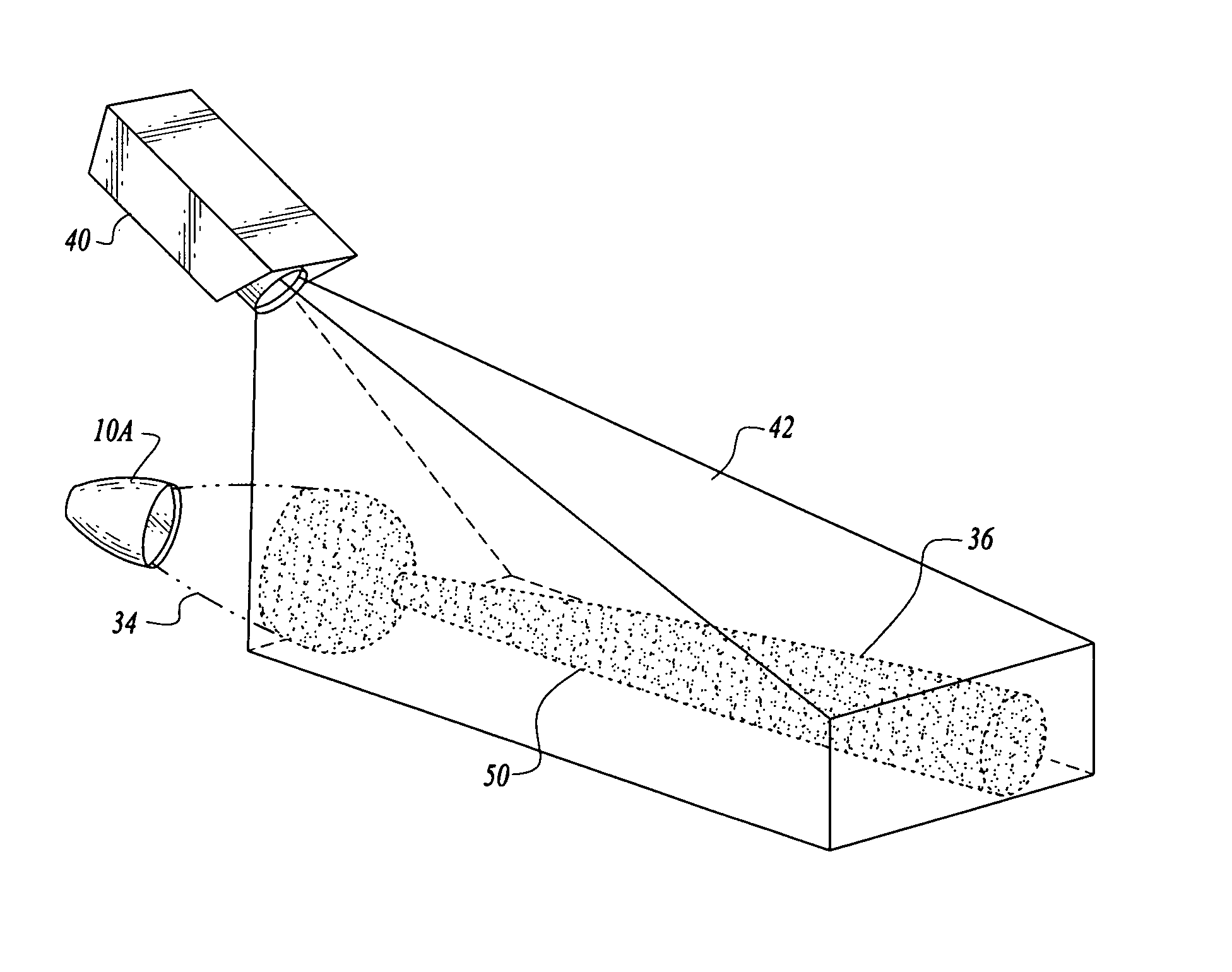
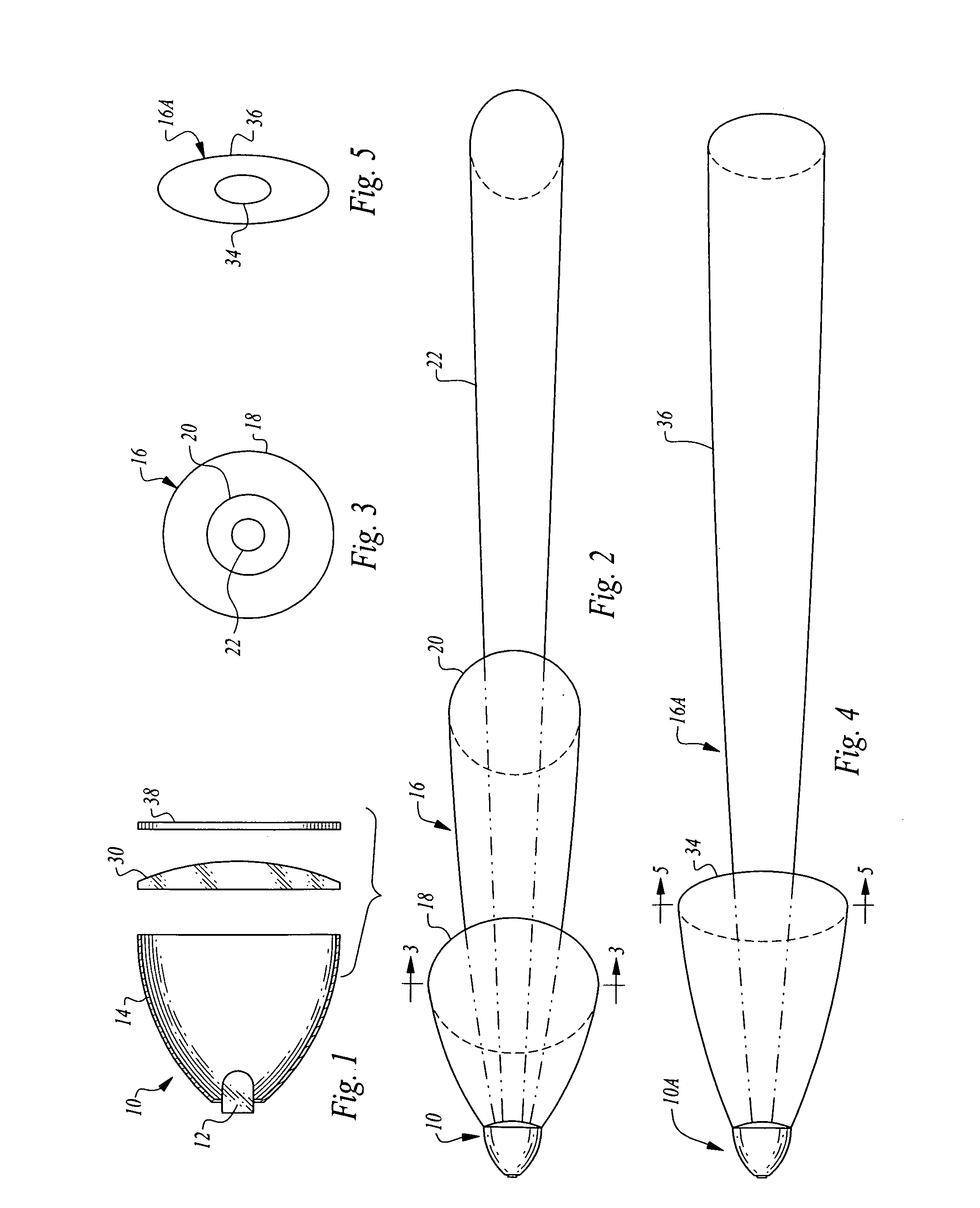
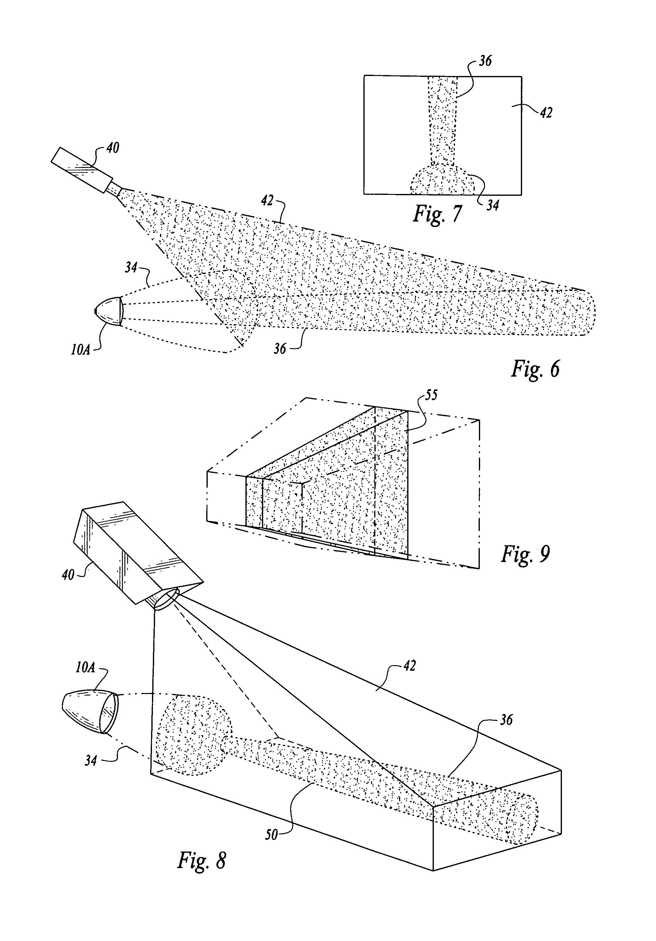
[0042]The drawing figures are not to scale and are for the purpose of illustrating the cooperative relationship between the structural elements of the system when practicing the present invention.

[0043]A conventional video camera with motion detection capability is of limited use for motion detection at night. To overcome this problem, light has to be added. However, adding light creates a number of issues. A light that can project illumination over a long distance requires high wattage and high power consumption. Further, a strong light can be a form of environmental pollution disturbing neighbors or wildlife. To limit the environmental impact, active infrared light in the low visibility or non-visible wave spectrum can be used. However, the cost of long-range active infrared light is high, and high also are the on-going maintenance cost of bulb replacement and cost of power consumption. Using a thermal camera is another option, but it costs even more. Most importantly, the high false


PUM


Abstract

A system for detecting intrusion into a space which includes motion detection light structure for producing and projecting a light pattern formed by a plurality of light beams of a certain character into a space and video motion detecting structure including a video camera having a field of view including at least some of the light pattern to detect intrusion into the light pattern. When motion is detected, images of the video camera are transmitted for threat assessment, and a scene illumination light is activated to improve visibility during nighttime operation.

Description


Claims


Application Information

Patent Timeline
Owner WONG THOMAS K
Why Eureka
Try Eureka