Method for determining corrections for artillery fire

a technology for artillery fire and correction methods, applied in the field of artillery fire, can solve the problems of high insufficient accuracy of 10 mrad, heavy and bulky, and add a non-negligent cost to the system

Active Publication Date: 2016-02-02
THALES SA
View PDF5 Cites 1 Cited by
  • Summary
  • Abstract
  • Description
  • Claims
  • Application Information

AI Technical Summary

Benefits of technology

[0036]This notably makes it possible to measure the distance between the observation system and the imp...

Problems solved by technology

Its disadvantage is linked to the sensitivity of this type of sensor, which is extremely sensitive to interference and in the best possible scenario is unable to guarantee a measurement to within less than 10 mrad.
Now this accuracy of 10 mrad is highly insufficient ...

Method used


Image

  • Method for determining corrections for artillery fire
  • Method for determining corrections for artillery fire
  • Method for determining corrections for artillery fire

Examples


Embodiment Construction

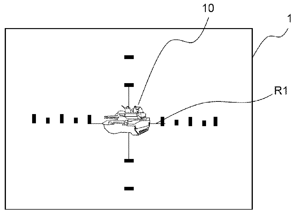
[0047]It is considered that a first firing often referred to as a test firing takes place after the transmission of the coordinates of the target to the artillery pieces. The observer awaits the impact of this test firing, keeping the crosshair R1 over the image of the target, without modifying the orientation of the observation system. R1 is generally at the center of the display screen 1.

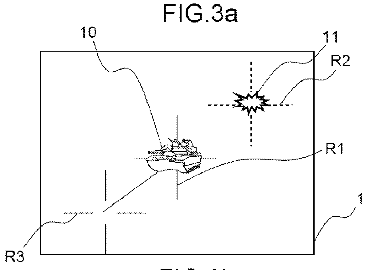
[0048]On impact, using means for displaying and moving a second crosshair R2 on the screen, the operator places this crosshair R2 over the image 11 of the impact point on the screen without modifying the orientation of the binoculars, as shown in FIG. 3a. These means for moving a crosshair comprise for example a joystick or pushbuttons or a device scanning the retina of the observer. Positioning the crosshair R2 over the image 11 of the impact point makes it possible to measure Δx (=horizontal offset of R2 relative to R1), which makes it possible to determine the offset in bearing with the very hi...


PUM


Abstract

A method determining artillery fire corrections toward a fixed target using a fixed observation system is oriented and equipped with a device measuring orientation of line of sight, a laser rangefinder, a positioning device, and a display screen with fixed crosshair, displaying and moving another crosshair. The method includes: orienting the observation system to display the central crosshair on the target image and calculating target geographical coordinates using distance provided by the rangefinder. If, after firing, the impact and target do not coincide, the method includes, if the orientation is fixed: displaying a second crosshair on the impact image and measuring offset between the two crosshairs, displaying a third crosshair symmetrical to the second crosshair; and orienting the optronic system to position the third crosshair on the target image, the first crosshair coinciding with the impact point image, and actuating the rangefinder to obtain distance between the system and impact.

Description

CROSS-REFERENCE TO RELATED APPLICATIONS[0001]This application is a National Stage of International patent application PCT / EP2013 / 057786, filed on Apr. 15, 2013, which claims priority to foreign French patent application No. FR 1201168, filed on Apr. 20, 2012, the disclosures of which are incorporated by reference in their entirety.FIELD OF THE INVENTION[0002]The field of the invention is that of artillery fire.BACKGROUND[0003]During artillery fire, a forward observer is placed between the artillery pieces and a fixed target, typically at approximately 1 or 2 km from the target, the artillery pieces being placed to the rear at a distance typically between 5 and 50 km for terrestrial artillery fire. This observer, who has a direct view of the target, is initially responsible for determining the position of this target. This is referred to as extraction of coordinates of the target.[0004]The latter are obtained in the following manner by means of a fixed but orientable optronic observa...

Claims


Application Information

Patent Timeline
Patent Type & Authority Patents(United States)
IPC IPC(8): G06G7/80F41G3/02F41G3/06F41G3/14
CPCF41G3/065F41G3/02F41G3/06F41G3/142
Inventor SEUGNET, PATRICKGODIO, STEPHANE
Owner THALES SA
Why Eureka
Try Eureka