Tire for driving on ice

Active Publication Date: 2016-12-27
MICHELIN RECH & TECH SA +1
View PDF18 Cites 0 Cited by
  • Summary
  • Abstract
  • Description
  • Claims
  • Application Information

AI Technical Summary

Benefits of technology

[0025]According to an advantageous variant, the sipe is extended radially inwards by a cavity, the cavity being dimensioned such that when the tread is worn and the cavity opens onto the rolling surface, the cavity forms a recess in the rolling surface. This allows the effect obtained by the tire according to the invention to last even longer. It is therefore possible to make the recesses last longer and maintain their effectiveness with respect to tread wear.

Problems solved by technology

The applicants have discovered that this reaching of an upper limit is in part due to the presence of ice splinters which originate when a stud scrapes the ice: if too great a quantity of splinters build up in the area of contact between the tire tread and the ice, the studs have less contact with the ice and lose some of their effectiveness.

Method used


Image

  • Tire for driving on ice
  • Tire for driving on ice
  • Tire for driving on ice

Examples


Example

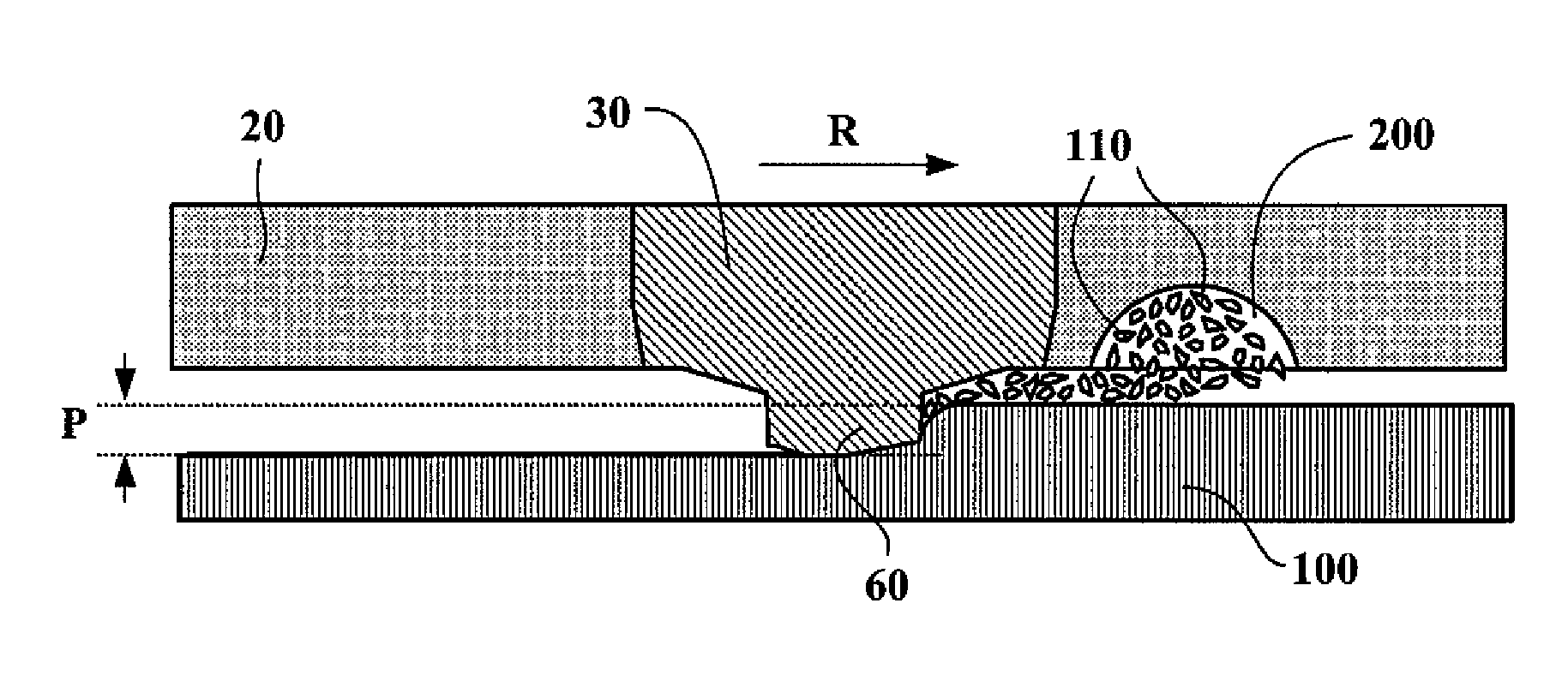
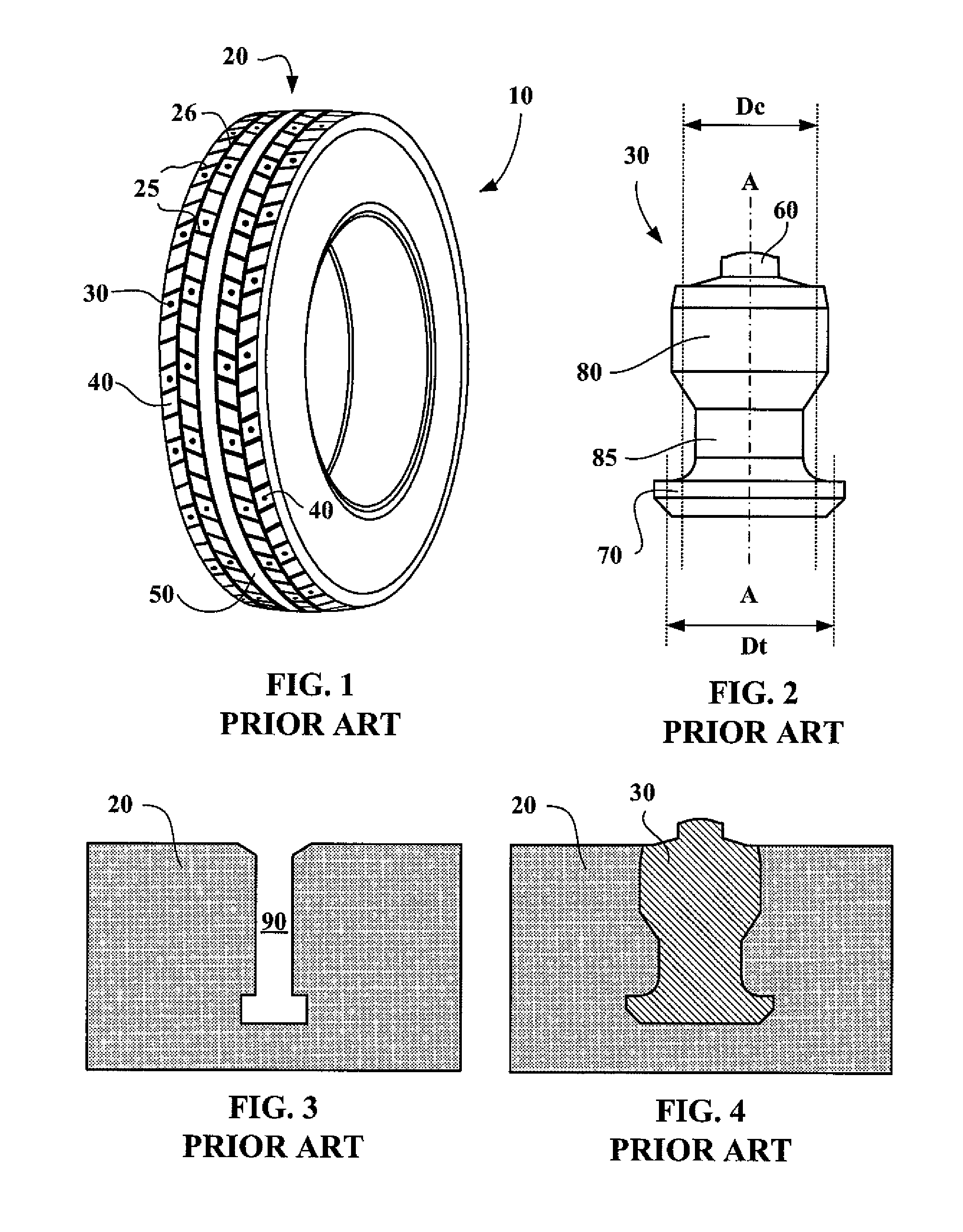
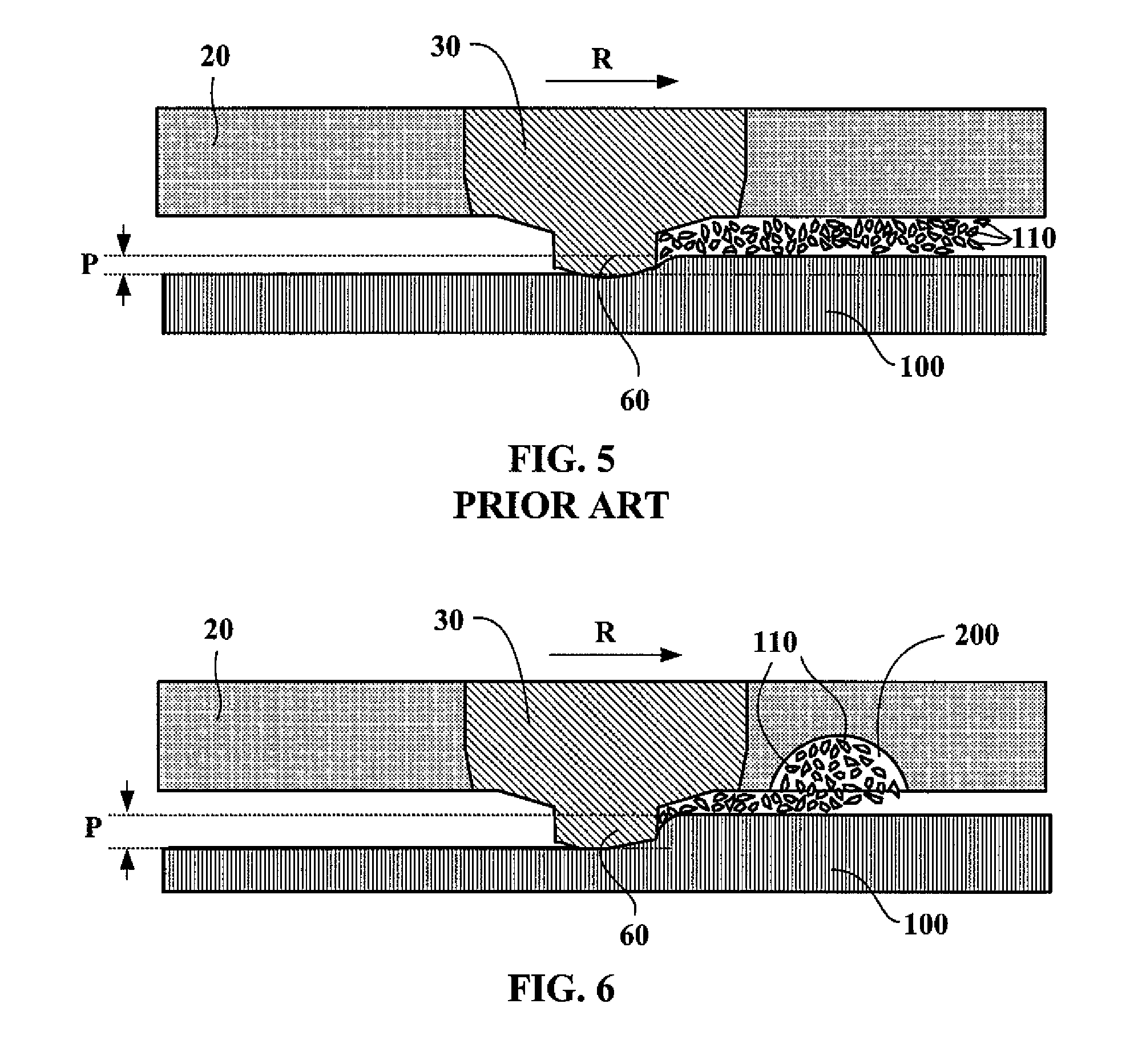
DETAILED DESCRIPTION OF THE DRAWINGS

[0035]The term “tire” here denotes any type of elastic tire whether or not in service it is subjected to an internal inflation pressure.

[0036]The term “groove” designates a cut-out in the tire tread that opens onto the rolling surface and the function of which is to evacuate water that has accumulated between the tire and the surface on which the tire rolls. Grooves may be circumferential or transverse. Typically, in a passenger car tire, they have a width of between 2 and 10 mm and a depth of about 8 mm. Grooves are distinguished from sipes in that sipes are much narrower (typically 0.3 to 1.5 mm) than grooves.

[0037]The term “stud” as used in this document is synonymous with the term “spike” also used in the prior art.

[0038]The term “recess” here denotes a hollow made in the rolling surface, the mean radial depth of which is greater than or equal to 1 mm.

[0039]The term “cavity” here denotes a cavity in the tread which does not directly open onto the


PUM


Abstract

A tire (10) for driving on ice, comprising: a tread (20) having a rolling surface configured to come into contact with the ground when the tire is rolling along; at least one stud (30) having a longitudinal axis (A-A), a part of the stud projecting from the rolling surface, the intersection between the stud and the plane tangential to the portion of the rolling surface around the stud forming a contour C, that part of the stud that projects from the rolling surface having a minimum cross section Sm, Sm corresponding to the smallest cross section of the said part in any plane containing the radial direction that passes through the point of intersection between the longitudinal axis of the stud and the plane tangential to the portion of the rolling surface around the stud; at least one recess (200) in the tread forming, on the rolling surface, a contour G, the recess being associated with the stud in that the minimum distance D between the contours C and G is less than or equal to 1 cm; in which, for each stud, the sum of the volumes Vn of the recesses associated with the stud, expressed in mm3, is greater than or equal to the product of the minimum cross section Sm of that part of the stud that projects from the tread, expressed in mm2, multiplied by a length of 50 mm.

Description


Claims


Application Information

Patent Timeline
Owner MICHELIN RECH & TECH SA
Why Eureka
Try Eureka