Refrigerator

A refrigerator and box door technology, applied in the field of refrigerators, can solve the problems of increased cost, need to set up other equipment, inconvenient use, etc., and achieve the effects of improving the utilization rate, fully filling, and flowing smoothly.

Active Publication Date: 2007-11-21
TAIZHOU LG ELECTRONICS REFRIGERATOR CO LTD
View PDF0 Cites 1 Cited by
  • Summary
  • Abstract
  • Description
  • Claims
  • Application Information

AI Technical Summary

Benefits of technology

This patented design allows an indoor unit (referred to also called a cooler) without any extra hardware or devices needed to produce ice from frozen food items. It achieves this through directing warm air into one area where it mixes well with water before being used to create ice. By placing these location fuzzy ribs near the cold gas channels at both ends, they help keep them apart while filling up space around their walls. Additionally, due to its placement within the sides of the chilled section, which helps reduce convection when hot gases pass over it, better temperature control occurs during use compared to traditional methods like circulation systems. Overall, this innovative technology enhances energy efficiency and reduces thermal losses caused by poor airflow management.

Problems solved by technology

This patented technical problem addressed in this patents relates to improving the design of conventional refrigzier devices such as those described earlier (see also discusses how they may include features like cool rooms and freezaces). These improvements aimed towards improved convenience during ice production while reducing costs associated therewith.

Method used


Image

  • Refrigerator
  • Refrigerator
  • Refrigerator

Examples


Embodiment Construction

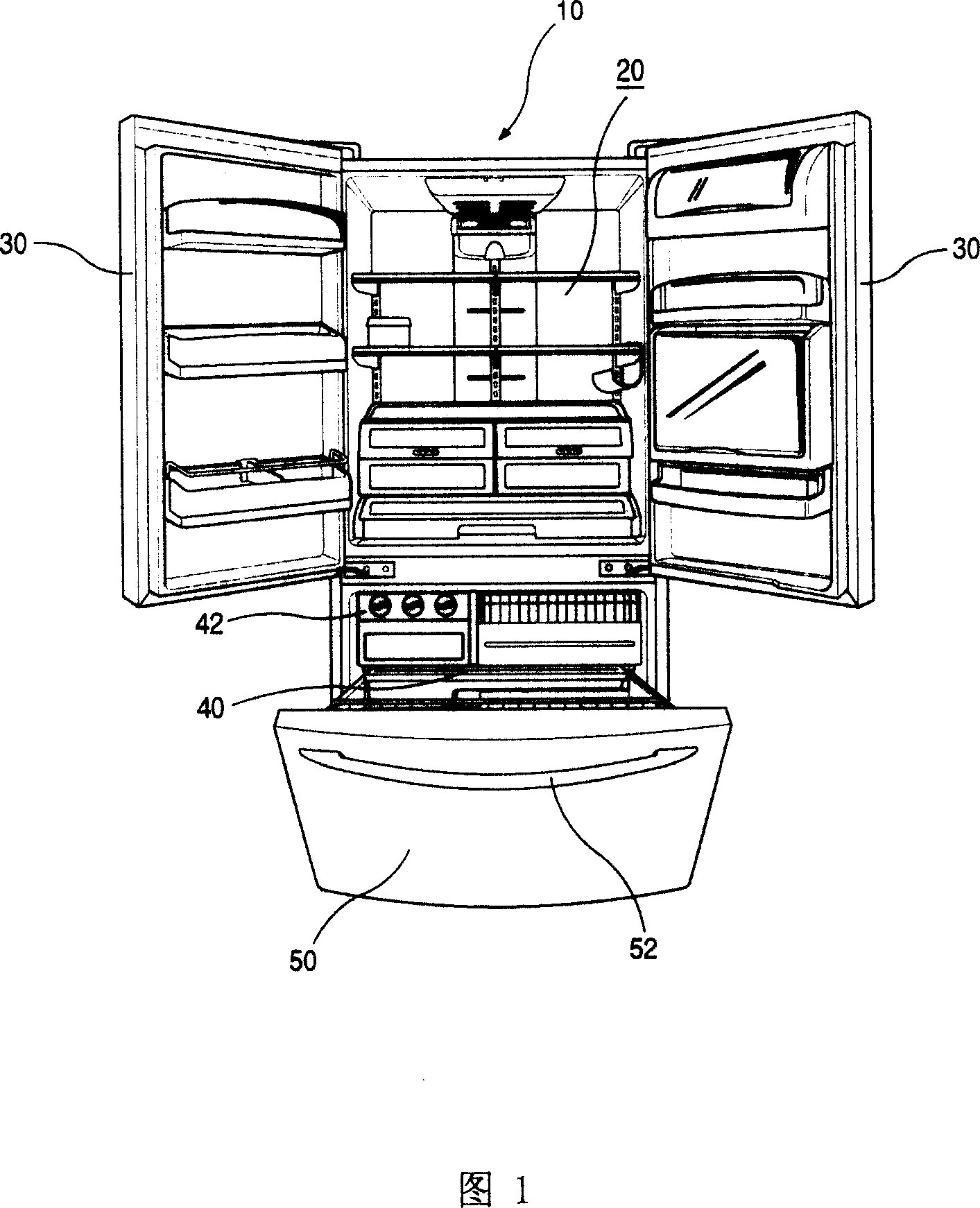
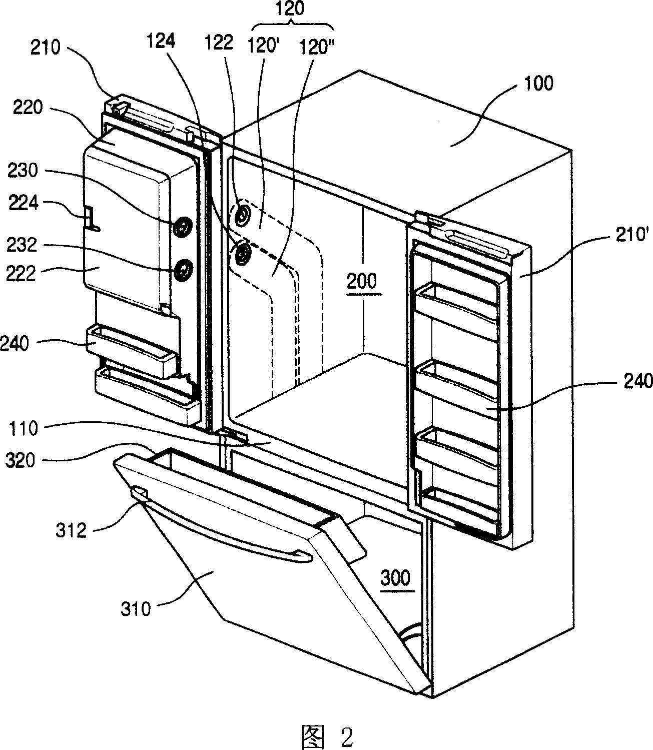
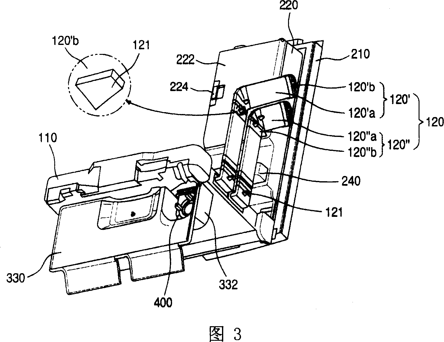
[0028] The refrigerator provided by the present invention will be described in detail below in conjunction with the accompanying drawings. Fig. 2 is a perspective view of the structure of the refrigerator provided by the present invention when the door is opened. Fig. 3 is a rear perspective view of part of the structure of the refrigerator provided by the present invention. As shown in FIG. 2 and FIG. 3 , the refrigerator main body 100 has a cube-shaped structure, on which are formed a refrigerating chamber 200 and a freezing chamber 300 for storing food. That is, the inside of the main body 100 is formed with a baffle 110 with a certain thickness, the upper side of the baffle 110 forms a refrigerating chamber 200 for refrigerating and preserving food, and the lower side of the baffle 110 forms a freezing chamber for freezing and preserving food. 300. In addition, a plurality of partitions not shown in the figure are arranged inside the refrigerator compartment 200 and the fre


PUM


Abstract

A refrigerator which includes a freezing room used to freeze food, storage room used to store food, the door of freezing and storage room on the front which can be choose to open and close, the cold air channel in the inside wall of the storage room which can introduce the cold air into the inside of the ice house and outside of which has a direction strip used to fix the channel in the centre of the inside wall of the storage room. This refrigerator is fixed the cold air channel inside the body, so part of the cold air supplied to the inside of freezing room can be to the ice house, at last there is no need to another equipment for the ice forming, and it can improve the efficient of the cold air usage. In addition, the direction strip on the cold air channel can make the channel be in the centre of the storage wall, so there is some space between the cold air channel and outside and inside of the case, at last the bubble liquid can flow more smoothly.

Description


Claims


Application Information

Patent Timeline
Owner TAIZHOU LG ELECTRONICS REFRIGERATOR CO LTD
Why Eureka
Try Eureka