Stud fastener and stabilising device

A technology of stabilizing devices and fixers, applied in the direction of fixing devices, machines/engines, hand tools suitable for fasteners, etc.

Inactive Publication Date: 2008-03-26
TELEZYGOLOGY
View PDF4 Cites 5 Cited by
  • Summary
  • Abstract
  • Description
  • Claims
  • Application Information

AI Technical Summary

Problems solved by technology

For example, a manual override may be necessary if there is no electrical power

Method used


Image

  • Stud fastener and stabilising device
  • Stud fastener and stabilising device
  • Stud fastener and stabilising device

Examples


Embodiment Construction

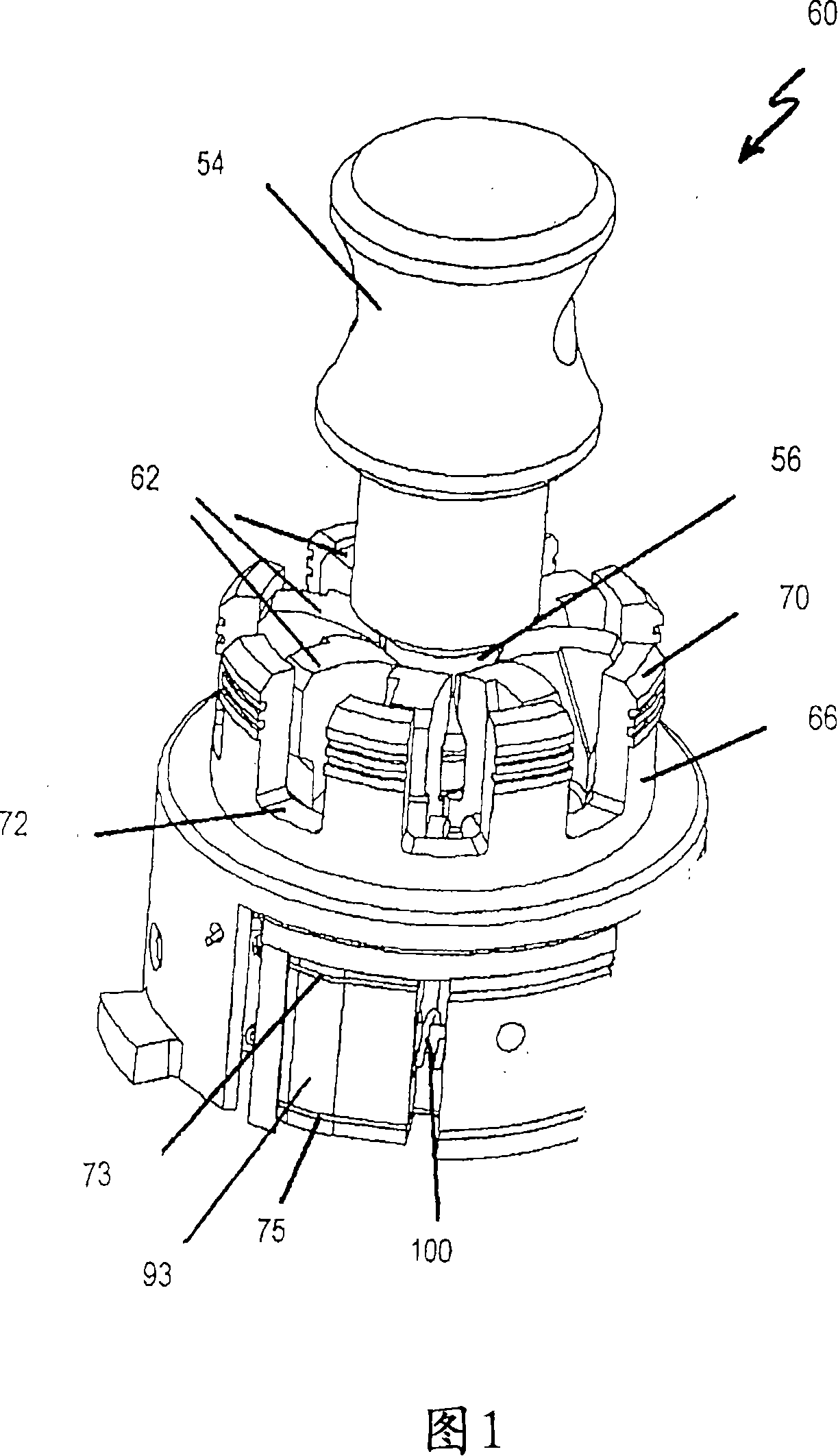
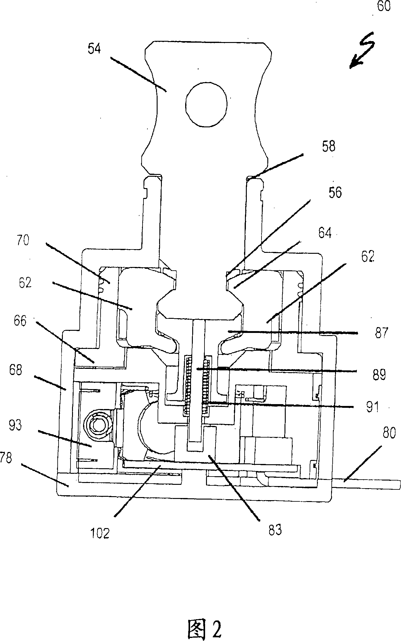
[0049] Referring to FIGS. 1-4 , the retainer 60 includes a stud 54 having a locking cavity that is a circumferential groove 56 . Retainer 60 includes bore 58 ( FIG. 2 ) into which stud 54 may be received by a push-fit.

[0050] The retainer 60 includes eight teeth 62 (three of which are labeled in FIG. 1 ), each tooth having a tongue 64 engageable with the groove 56 ( FIG. 2 ).

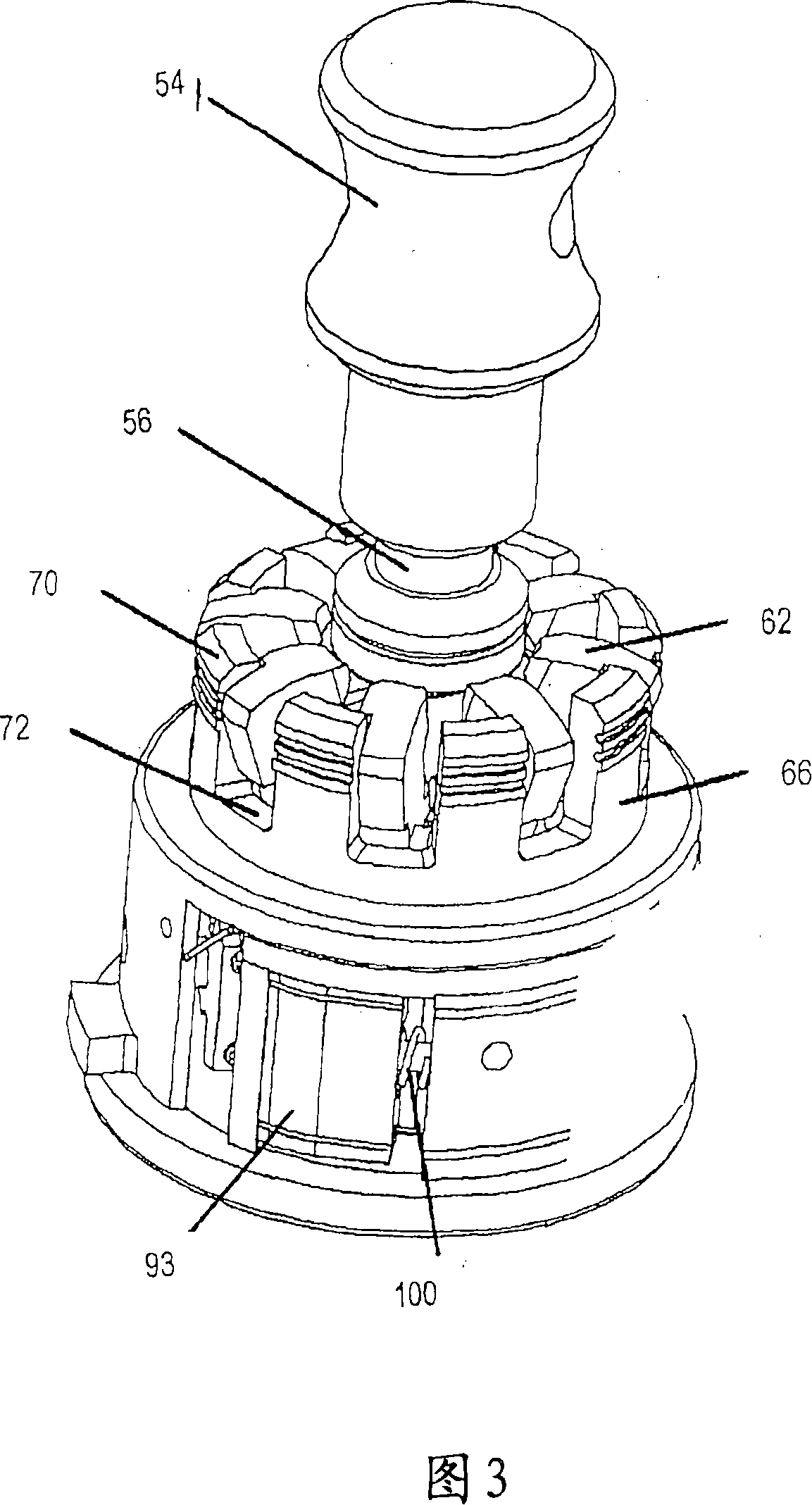
[0051] The shuttle 66 is mounted for rotation within the outer housing 68 between two positions. The first position is shown in FIGS. 1 and 2 , wherein the locking protrusion 70 retains the tooth 62 in the recess 56 of the stud 54 in the locked position when the stud 54 is in the bore 58 . The second position is shown in FIGS. 3 and 4 , wherein the shuttle 66 has been rotated sufficiently so that the teeth 62 are located in the holes 72 between the locking projections 70 . In this state, the tooth 62 no longer maintains the locked position, ie in the groove 56 in the stud 58 .

[0052] Shuttle 66 is r


PUM


Abstract

The invention relates to a stabilising device (120) for an assembly which includes two shape memory alloy wires (104, 106) adapted to operate in conjunction. The stabilising device (120) includes a rocker plate (108) for attachment to each of the shape memory alloy wires; the rocker plate (108) is adapted to pivot when one shape memory alloy wire (104 or 106) is subjected to a stress greater than that to which the other shape memory alloy wire (106 or 104) is subjected, in order to reduce the stress on the first-mentioned shape memory alloy wire. The invention further relates to a fastener (60) including a stud (54) having a locking cavity (56), an aperture (58) adapted to receive the stud (54), a locking means (teeth) (62) adapted to engage the locking cavity (56), a shuttle (66) rotatable by a rotating means including material adapted to contract when activated and a plug (87) slidable within the shuttle (66) to close off the aperture (58) when not occupied by the stud (54). The shuttle (66) is rotatable by the rotating means between a locking position, in which the locking means (teeth) (62) engages the locking cavity (56), and an unlocking position in which the locking means (teeth) (62) does not engage the locking cavity (56). The plug (87) can help to prevent contamination of the fastener (60).

Description


Claims


Application Information

Patent Timeline
Owner TELEZYGOLOGY
Why Eureka
Try Eureka