Service protecting method for automatic exchange optical network
A service protection and automatic exchange technology, applied in the field of communication, can solve problems such as defects in the utilization of resources and no technical solutions have been proposed yet.
- Summary
- Abstract
- Description
- Claims
- Application Information
AI Technical Summary
Benefits of technology
Problems solved by technology
Method used
Image

Examples
example 1
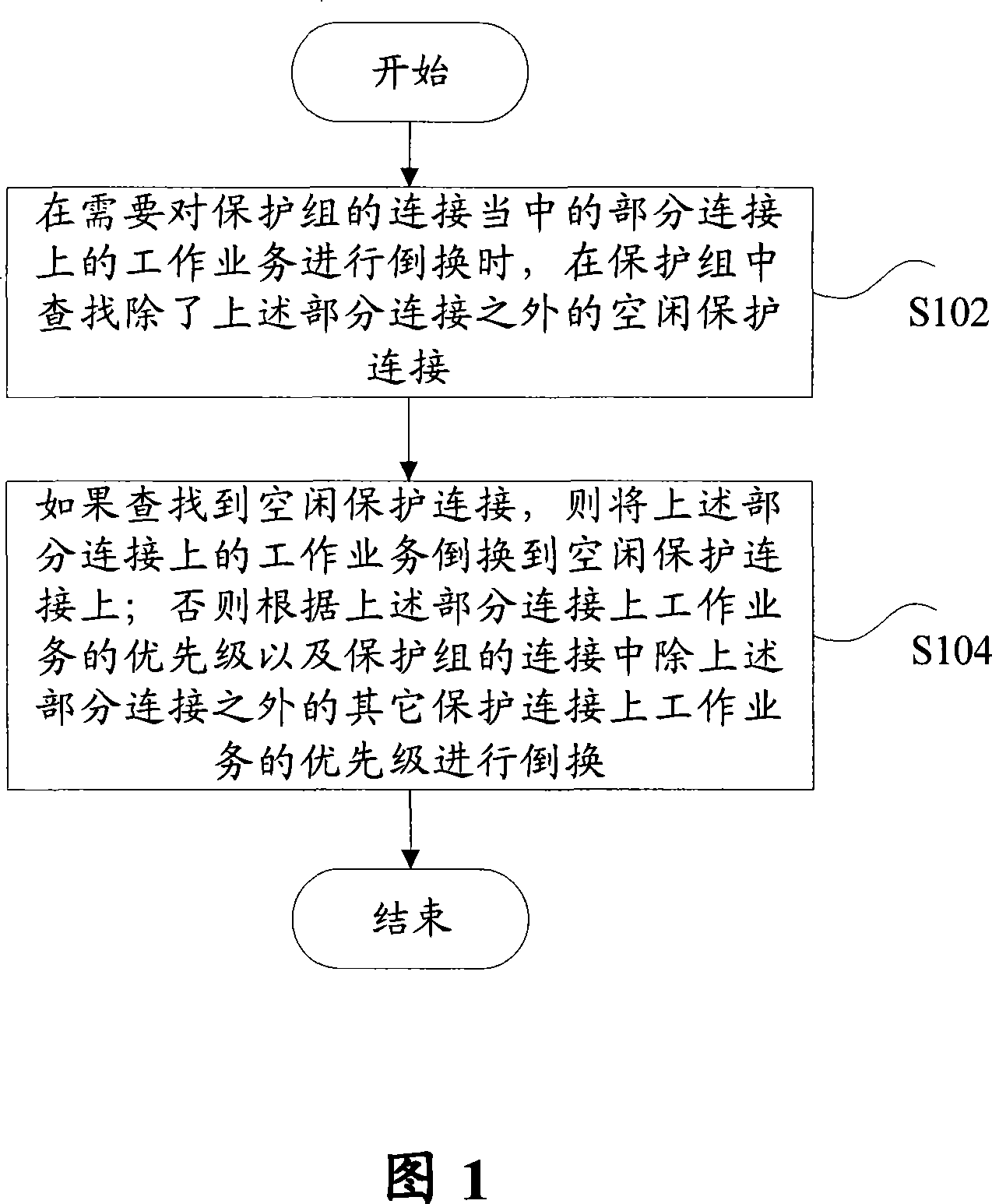
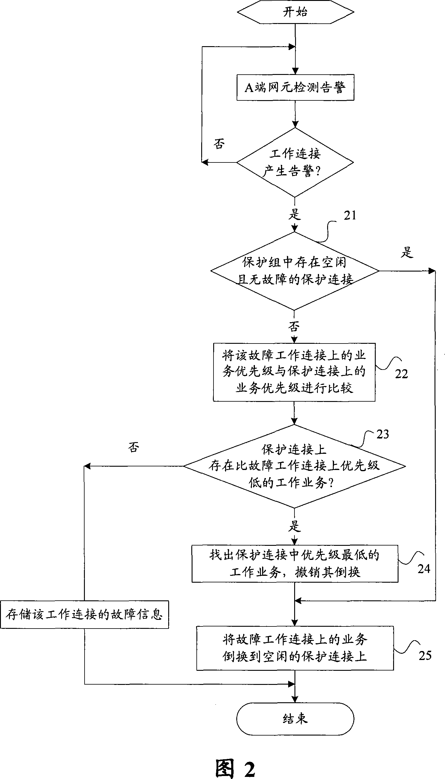
[0046] Example 1: The network element detects the alarm information on the working connection
[0047] Combined with Figure 2, Figure 6, and Figure 7, the services on the working connection W2 in the protection group have been switched to the protection connection P1, and the services on the working connection W4 have been switched to the protection connection P2; at this time, the A-side network element detects Working connection W1 failed. The following will use this scenario to describe in detail the specific steps for the M:N protection group to implement protection switching when the A-side network element detects the alarm information on the working connection:
[0048] Step 21: Find the faulty working connection W1, and check whether there is an idle protection connection in the protection group;
[0049] Step 22: There is no idle protection connection in the protection group, compare the priorities of the working services on W1, W2 and W4;
[0050] Step 23: On the prote
example 2
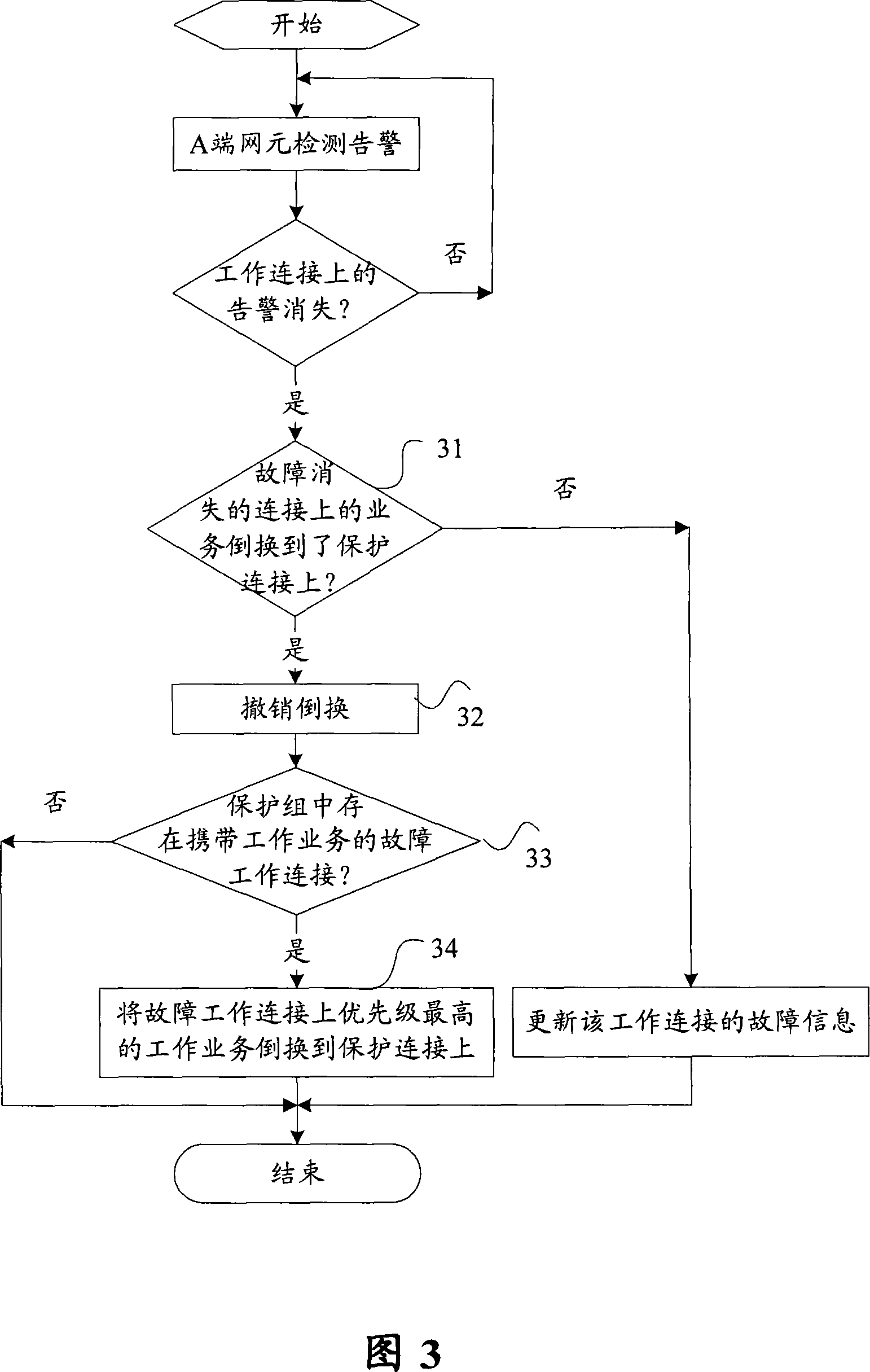
[0053] Instance 2: The failure on the working connection disappears
[0054] Combining Figure 3, Figure 6, and Figure 7, in this example, the services on the working connection W1 in the protection group are switched to the protection connection P2, the services on the working connection W2 are switched to the protection connection P1, and the working connections W3, There are alarms on W4; at this time, the A-side network element detects that the fault on the working connection W2 disappears. The following will use this scenario to describe in detail the specific steps for the M:N protection group to implement protection switching when the A-side network element detects that the alarm on the working connection disappears:
[0055] Step 31: find out the working connection W2 where the fault disappears, and check whether the service on W2 has been switched to the protection connection;
[0056] Step 32: The service on W2 is switched to the protection connection P1, and its switch
example 3
[0059] Example 3: Alarm on protected connection
[0060] Combining Figure 4, Figure 6, and Figure 7, in this example, the service on the working connection W1 in the protection group is switched to the protection connection P2, and P1 is idle; at this time, the A-side network element detects an alarm on the protection connection P2 . The following will use this scenario to describe in detail the specific steps for the M:N protection group to implement protection switching when the A-side network element detects the alarm information on the protection connection:
[0061] Step 41: find out the faulty protection connection P2, and check whether there is a working service being protected on P2;
[0062] Step 42: find out the idle protection connection P1 in the protection group;
[0063] Step 43: Switch the working service on the protection connection P2 to the protection connection P1.
PUM
 Abstract
Description
Claims
Application Information
 - R&D Engineer
- R&D Manager
- IP Professional
- Industry Leading Data Capabilities
- Powerful AI technology
- Patent DNA Extraction
Browse by: Latest US Patents, China's latest patents, Technical Efficacy Thesaurus, Application Domain, Technology Topic.
© 2024 PatSnap. All rights reserved.Legal|Privacy policy|Modern Slavery Act Transparency Statement|Sitemap