Car engine timing system

A kind of technology of automobile engine, which is applied in the direction of engine components, machines/engines, mechanical equipment, etc., can solve the problems of timing system assembly and maintenance difficulties, and achieve the effect of convenient installation and maintenance

Inactive Publication Date: 2008-05-21
CHERY AUTOMOBILE CO LTD
View PDF0 Cites 1 Cited by
  • Summary
  • Abstract
  • Description
  • Claims
  • Application Information

AI Technical Summary

Benefits of technology

This technology allows for easy assembly or maintaining an accurate timing mechanism without leaking any grease from inside it due to its design featuring adding a covering over both components before they go into use. Additionally, this design prevents contamination with foreign objects while still allowing proper functioning of the device's timing chains and gears.

Problems solved by technology

The technical problem addressed by this patented technology relates to improving the performance and reliability of timing systems that use timings inside these components without requiring them being installed separately from other components due to their poorly-sealed joints between different parts. This requires frequent replacements overall making maintenance tasks more challenging than usual.

Method used


Image

  • Car engine timing system
  • Car engine timing system
  • Car engine timing system

Examples


Embodiment Construction

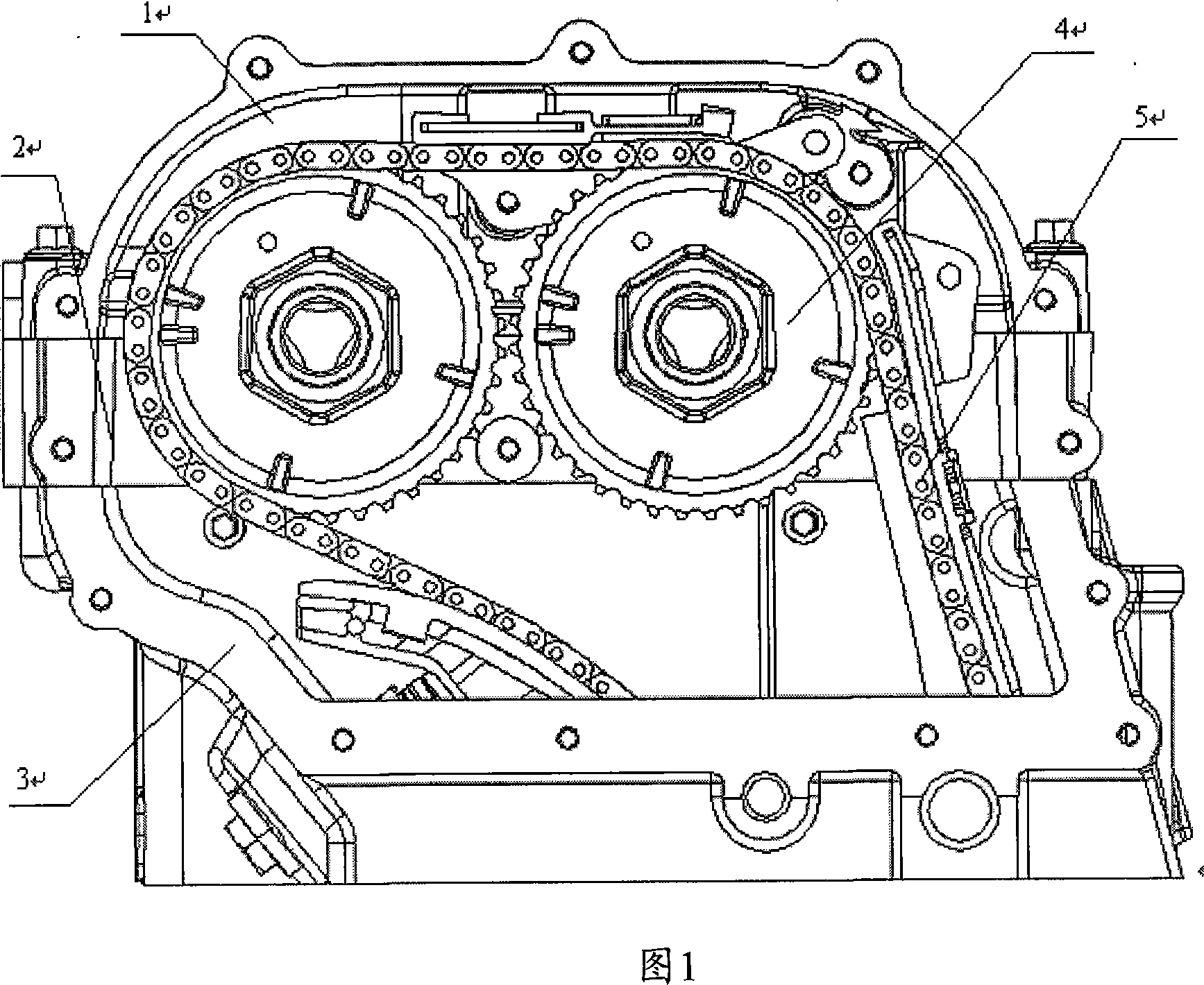
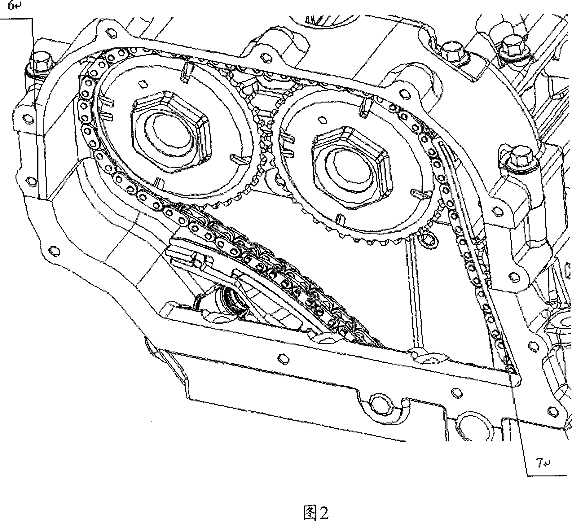
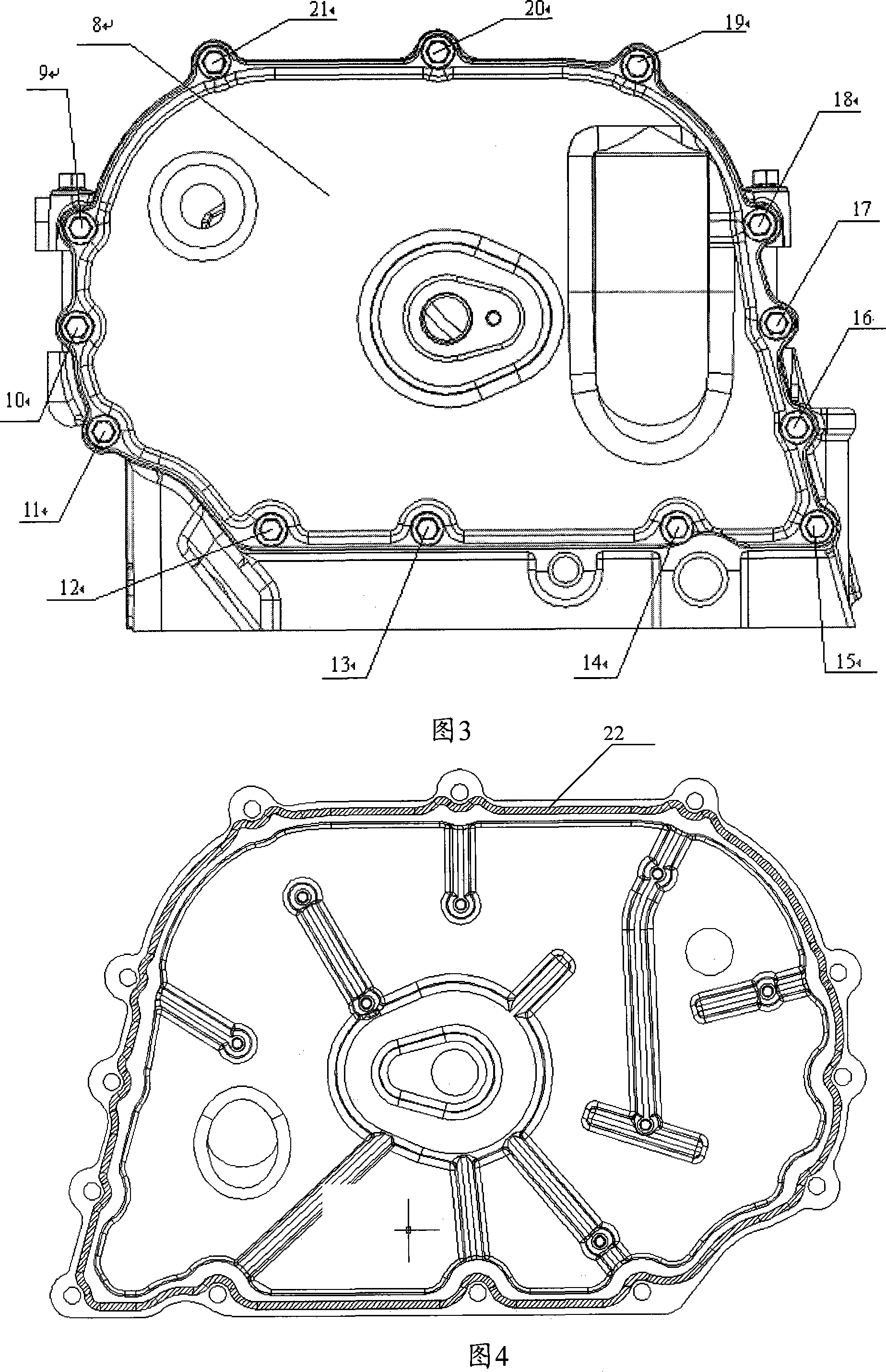
[0015] As shown in Figure 1-3, starting from the convenience of assembly and maintenance, plan enough space as the timing chamber, and then design it to the cylinder head 3, the lower camshaft frame 2 and the upper camshaft frame 1 (or valve chamber cover). Then install the cylinder head, lower camshaft frame and upper camshaft frame (or valve chamber cover) in sequence. A cover 8 is added to the timing chamber formed by the cylinder head 3 and the upper and lower camshaft frames 1 and 2, and the cover and the cylinder head, upper and lower camshaft frames are connected together by fastening bolts 9-21 and sealant to form a closed cavity. This not only ensures the convenience of installation and maintenance of the timing chain 5 and the sprocket 4, but also ensures that the lubricating oil necessary for the normal operation of the timing system will not leak out, and at the same time, external dust will not enter the timing chamber and affect the timing. The system works. It c


PUM

PropertyMeasurementUnit
Widthaaaaaaaaaa

Abstract

The present invention discloses an engine timing chamber structure. A cylinder head (3), an upper cam shaft frame (1) and a lower cam shaft frame (2) form the timing chamber; a timing chamber head (8) is added outside the timing chamber; the timing chamber head (8), the cylinder head (3), the upper cam shaft frame (1) and the lower cam shaft frame (2) are connected through a plurality of fastening bolts (9, 10, to,21) and a seal glue, thus forming an enclosed hollow cavity. The method of painting the flat anaerobic seal glue is adopted to seal the cylinder head (3) and the lower cam shaft frame (2) as well as the upper cam shaft frame (1) and the lower cam shaft frame (2); the timing chamber adopts silicon rubber sealing. The timing chamber structure provided by the present invention ensures not only the convenient installation and maintenance of the timing chain and the chain wheel but also no lubricant leakage required by the normal operation of the timing system; at the same time, the dust outside is unable to enter the timing chamber and affect the operation of the timing system. The present invention not only solves the installation and maintenance of the timing system but also simplifies the structure of the cylinder head and the cam shaft frame.

Description


Claims


Application Information

Patent Timeline
Owner CHERY AUTOMOBILE CO LTD
Why Eureka
Try Eureka