Internal multiband antenna

An antenna and working frequency band technology, applied in the field of internal multi-band antennas, can solve problems such as low working frequency bands

Inactive Publication Date: 2008-06-25
PULSE FINLAND
View PDF1 Cites 32 Cited by
  • Summary
  • Abstract
  • Description
  • Claims
  • Application Information

AI Technical Summary

Problems solved by technology

The antenna also has a relatively narrow lower operating frequency band and the resulting disadvantage

Method used


Image

  • Internal multiband antenna
  • Internal multiband antenna
  • Internal multiband antenna

Examples


Embodiment Construction

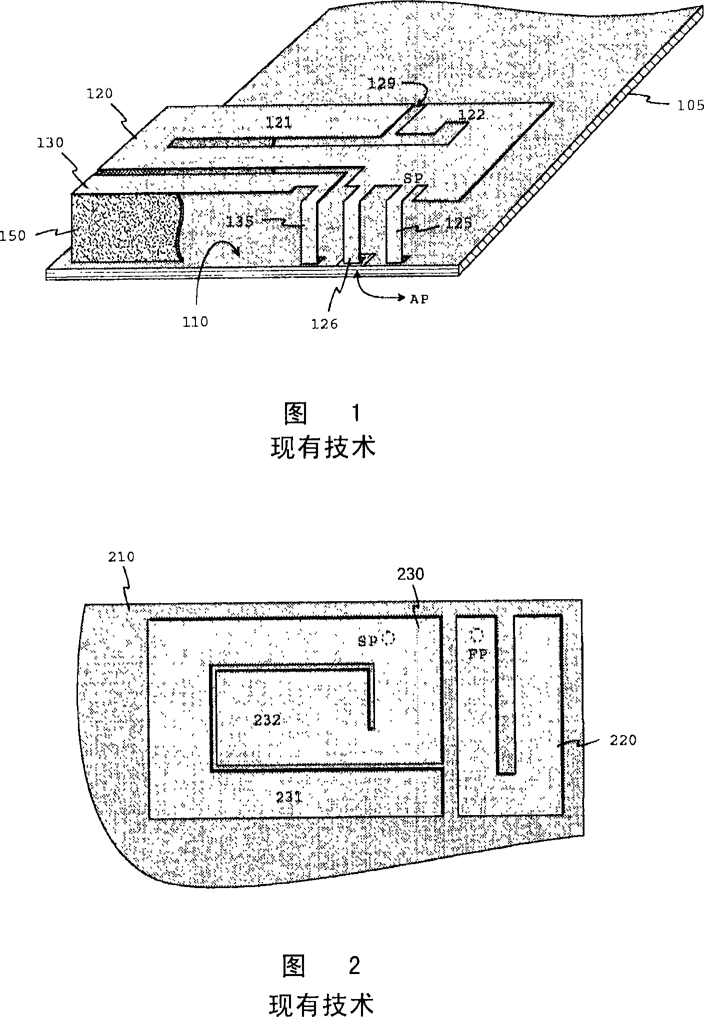
[0023] Figures 1 and 2 have already been discussed in conjunction with the description of the prior art.

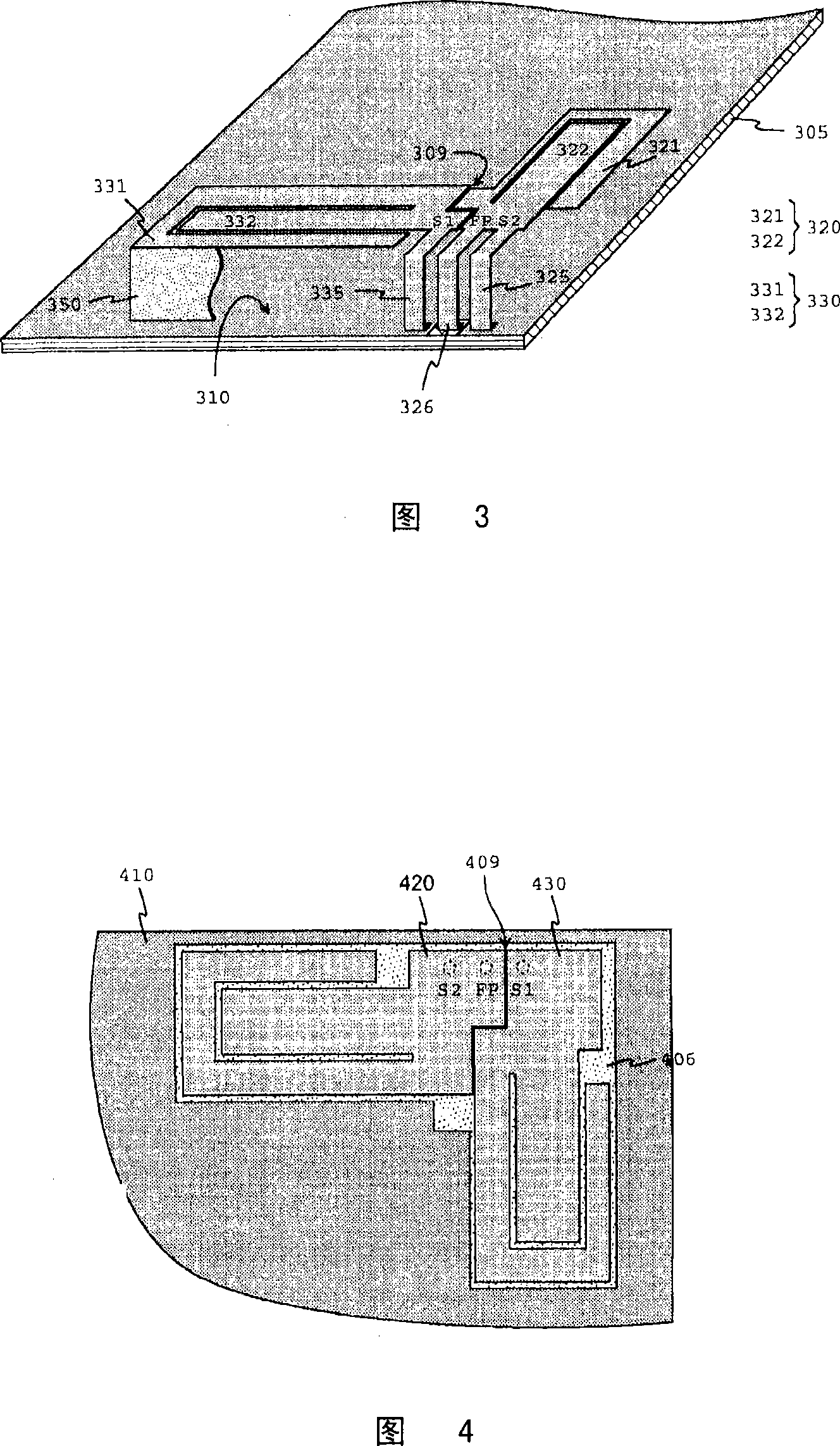
[0024] Figure 3 shows an example of a multiband antenna inside a radio according to the invention. The antenna in this embodiment has two operating frequency bands, a lower and an upper, but the number of frequency bands used by the different radio systems in which the antenna operates is very large. The rectangular circuit board 305 of the radio can be seen in the figure, the conductive upper surface of which acts as a ground plane 310 for the antenna. On the ground plane, there are two planar radiating elements of the antenna located substantially on the same geometric plane: the main element 320 and the parasitic element 330 . The main element is connected to the antenna port of the radio device through the feed conductor 326 and to the ground plane through the second short-circuit conductor 325, thus constituting the PIFA together with the ground plane. The feed con...


PUM


Abstract

A multiband antenna intended for small-sized radio devices, internal to the device. The antenna comprises a main element (320) connected to the antenna feed conductor (326) and a short-circuited parasitic element (330). The feed point (FP) is beside the short-circuit point (S1 ) of the parasitic element. The elements are typically elongated, and at least their parts, which correspond a certain operating band, are substantially perpendicular to each other. Two resonances, the frequencies of which fall on two different operating bands of the antenna, are excited also in the parasitic element. In order to implement the resonances of the parasitic element, the coupling between the elements takes place through a very narrow slot (309) near the feed point and the short-circuit point of the parasitic element. The coupling is then sufficiently strong in spite of the positions of the main and the parasitic element. Even the lower operating band of the antenna can be made so wide that it covers the frequency ranges of two different systems.

Description

technical field [0001] The present invention relates to internal multi-band antennas for small radios in which parasitic elements are utilized. The invention also relates to a radio device with an antenna according to the invention. Background technique [0002] In mobile base stations it is already common to have modules that can operate in two or more systems using different frequency ranges, for example the different GSM systems (Global System for Mobile Communications). A basic condition for the operation of a mobile base station is that the transmission and reception characteristics of its antenna satisfy the frequency bands of all systems used. It is relatively easy to fabricate high-quality multiband antennas without size constraints. However, in mobile base stations, especially in mobile phones, the antenna must be small in size when it is placed inside the housing of the device for ease of use. This causes the design of antennas to become a more demanding task. ...

Claims


Application Information

Patent Timeline
IPC IPC(8): H01Q1/24H01Q9/04H01Q5/00H01Q1/38H01QH01Q5/10H01Q5/371H01Q5/392H01Q21/24
CPCH01Q5/0068H01Q9/0421H01Q1/243H01Q21/24H01Q5/371H01Q5/0058H01Q9/0457H01Q5/392H01Q9/0442H01Q1/24H01Q1/38H01Q5/00H01Q9/04
Inventor P·克斯基塔洛P·普西南
Owner PULSE FINLAND
Why Eureka
Try Eureka