Aging room used for the last assembling process of LCD screen

A liquid crystal display and aging room technology, applied in the field of aging room, can solve the problems of high energy consumption and low efficiency, and achieve the effects of reasonable layout, simple and convenient operation, and shortening the aging waiting time.

Inactive Publication Date: 2008-08-06
萧富壬
View PDF0 Cites 5 Cited by
  • Summary
  • Abstract
  • Description
  • Claims
  • Application Information

AI Technical Summary

Problems solved by technology

The efficiency of the test is relatively low, and because a certain temperature is required during the test, the test must be complet

Method used


Image

  • Aging room used for the last assembling process of LCD screen
  • Aging room used for the last assembling process of LCD screen
  • Aging room used for the last assembling process of LCD screen

Examples


Embodiment Construction

[0029] Below in conjunction with accompanying drawing, further illustrate the structure of aging room of the present invention.

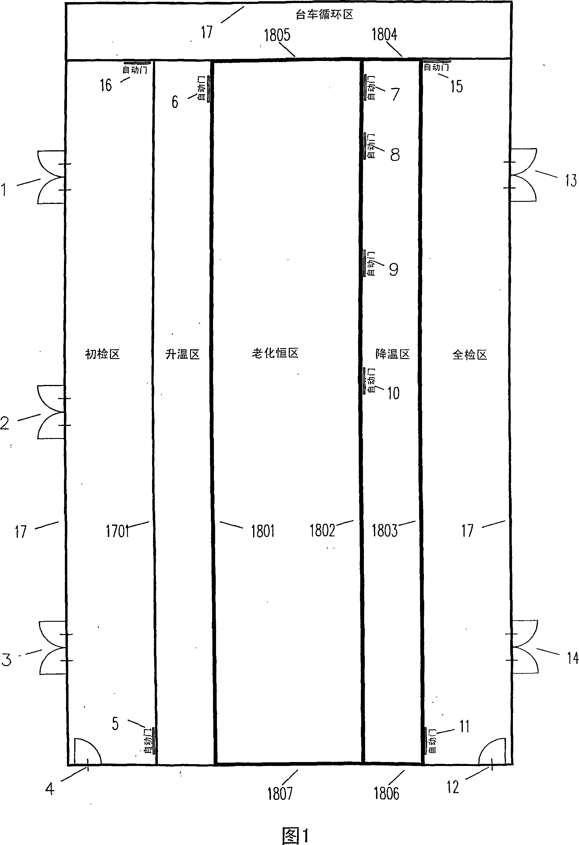
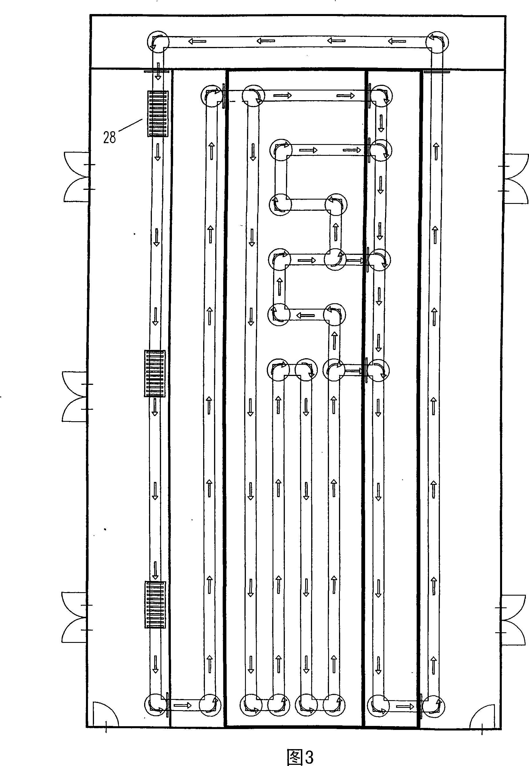
[0030] Fig. 1, Fig. 2, Fig. 3 are the structural schematic diagrams of the aging chamber of the present invention.

[0031] As shown in FIG. 1, the aging chamber of the present invention is composed of an outer wall 17 and an outer cover. The aging room includes a preliminary inspection area, a heating area, an aging constant temperature area, a cooling area and a full inspection area.

[0032] There are display screen inlets of different sizes corresponding to different size display screens on the outer wall of the preliminary inspection area. In this embodiment, there are three screen inlets 1, 2, 3 of different sizes.

[0033] Located between the initial inspection area and the heating area, there is a next door 1701 with the entrance 5 of the heating area;

[0034] There is a first insulation wall 1801 with an inlet 6 of the constant temperature


PUM


Abstract

An aging room used for the last assembling process of LCD panel modules includes a primary test area, a heating area, a constant temperature area, a cooling area, a full test area and a trolley cycle area. It also includes a loading track, a heating track, an aging test track, a cooling track, a full test track and a trolley cycle track that lies in each said area correspondingly. In correspondence with the sizes of LCD panels, various inlets are disposed in the outward wall of the primary test area; various trolleys used for carring LCD panels are provided on the tracks; various aging test tracks that have different lengths according to the aging times necessary for each size of LCD panels are provided in the constant temperature area; and various outlets are provided. Accordingly, the aging room could test various sizes of LCD panels in the same time, thus reduces the wait time for aging test and increase the efficiency. Furthermore, the trolleys are used circularly in the aging room such that the energy loss is reduced.

Description


Claims


Application Information

Patent Timeline
Owner 萧富壬
Why Eureka
Try Eureka