Production technique of LED luminous laminated glass

A manufacturing process and luminous interlayer technology, applied in semiconductor/solid-state device manufacturing, electrical components, building components, etc.

Inactive Publication Date: 2008-12-10
上海耀皮建筑玻璃有限公司 +1
View PDF0 Cites 16 Cited by
  • Summary
  • Abstract
  • Description
  • Claims
  • Application Information

AI Technical Summary

Benefits of technology

This patented technology allows for use either single type of glass (curtain walls) or combined types of glass like double glazings. It also includes design features such as LED placement patterns along one side of each piece of glass, which controls how much energy from an external source enters into them when turned back on compared to traditional methods where all lights have been lit simultaneously. Overall this results in improved efficiency and effectiveness over existing technologies.

Problems solved by technology

The technical problem addressed by this patented technology relates to improving the durability and weld resistance of solar energy systems without damaging their performance or causing any issues during installation on buildings' surfaces such as rainwater penetrations caused by water droplets impacted from precipitation.

Method used


Image

  • Production technique of LED luminous laminated glass

Examples


Embodiment Construction

[0037] In this implementation case, laser engraving is used to carve the LED conductive circuit on the conductive coated glass plate, and tinned copper strips are used as power leads, and the LED and tinned copper strips are bonded to the conductive coating with special conductive adhesive. On the glass plate, the drying temperature is 150°C. The LED conductive coated glass plate after drying is shown in the attached figure. 15 LEDs are designed and arranged on the conductive glass plate, which are divided into 5 groups vertically, and each group consists of three LEDs connected in series.

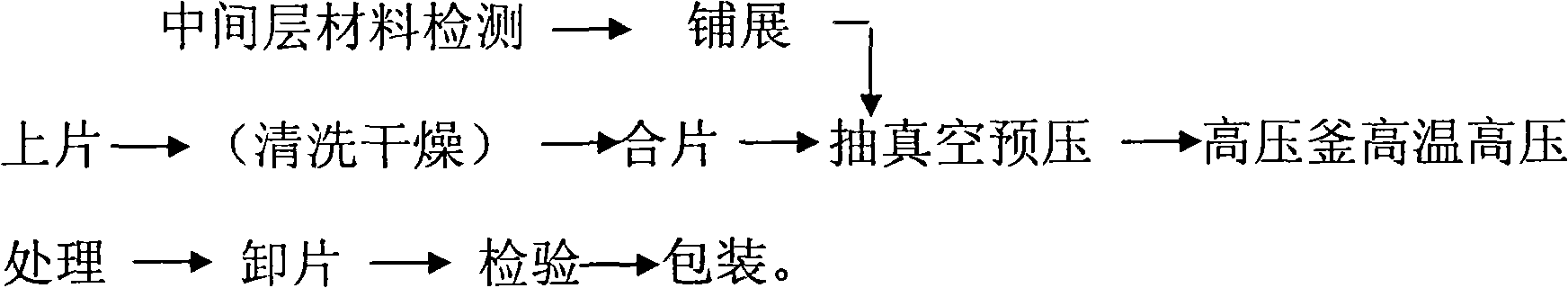
[0038] In this implementation case, the processing process of luminescent laminated glass is as follows:

[0039]

[0040] In this implementation case, the selected middle layer is PVB material with a total thickness of 1.52mm. The laminated film room has a cleanliness of more than 100,000 grades, an ambient relative humidity of 25%, and an ambient temperature of 23°C.

[0041] In this


PUM


Abstract

The invention provides a manufacturing technique of a luminous LED sandwich glass capable of luminous with controlled luminous effect; a film structure of the LED sandwich glass includes a glass plate, an adhesive layer, a LED layer and a conductive coated glass plate in order. The main manufacturing steps are as follows: cleaning and drying the conductive coated glass plate, scribing a pre-designed LED circuit thereon, adhering LED and a power source lead, drying it, paving the intermediate adhesive layer, closing sheets, undergoing vacuuming and pre-pressing high pressure and temperature treatments of a high-pressure autoclave; designing various LED layout circuits on the LED luminous sandwich glass, so as to control luminous quantity, luminous effect and various luminous acts of the whole glass.

Description


Claims


Application Information

Patent Timeline
Owner 上海耀皮建筑玻璃有限公司
Why Eureka
Try Eureka