Precision filter

A precision filter and filter technology, which is applied in the direction of fixed filter elements, filter separation, chemical instruments and methods, etc., can solve the problems of poor filtering effect, deviation of measurement results, and affecting the accuracy of sensors, etc., so as to achieve convenient use, good effect

Inactive Publication Date: 2009-06-17
薛文伟
View PDF0 Cites 0 Cited by
  • Summary
  • Abstract
  • Description
  • Claims
  • Application Information

AI Technical Summary

Benefits of technology

This technology uses special materials that are resistant against chemical agents like acids or bases during cleaning processes for filters used with equipment such as gas purifiers. These materials have good filtration properties but they can be difficult to remove from their mountings due to tight fitting between them and difficulty accessing certain areas within these systems' internal structure without damaging sensitive components inside.

Problems solved by technology

This patented technical problem addressed by this patents relates to measuring high-purity gases with filters that can collect small amounts of dirt or other particles during operation without interferring their measurements accurately due to these factors. Current methods involve removing them manually after every few hours before starting analysis again which makes maintenance difficult and reduces efficiency.

Method used


Image

  • Precision filter

Examples


Embodiment Construction

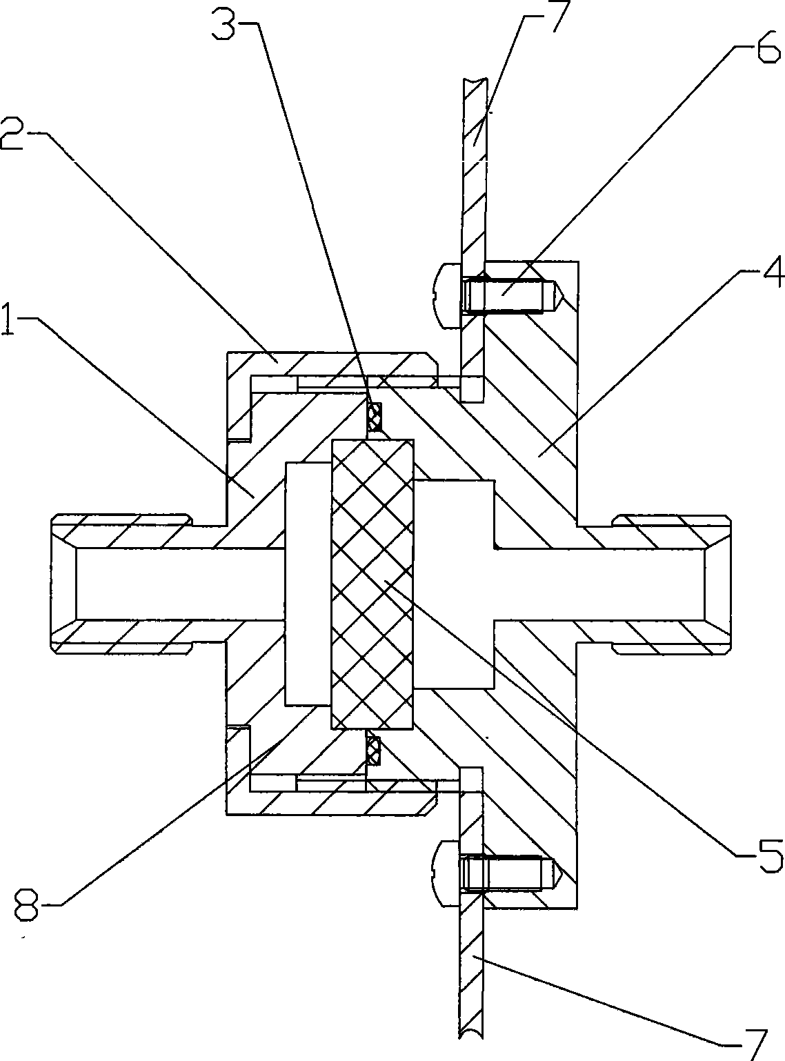
[0011] Examples such as figure 1 As shown, a precision filter includes a filter cover 1 and a filter base 4. The filter cover 1 has a boss 8, the filter cover 1 and the filter base 4 are connected, and the filter base 4 has external threads. A round nut 2 is arranged between the filter cover 1 and the filter base 4, and the round nut 2 connects the filter cover 1 and the filter base 4 through the boss 8 and the external thread, and the filter cover 1 and the filter base 4 is provided with a filter element 5, the filter element 5 is made of polymer sintered polytetrafluoroethylene, the contact between the filter cover 1 and the filter base 4 is provided with an O-shaped gasket 3, and the filter base 4 is passed through the bolt 6 is fixed on the fixed plate 7.


PUM


Abstract

The present invention relates to a precise filter, which comprises a filter cover and a filter base. A lug boss is arranged on the filter cover, and the filter cover and the filter base are communicated. The filter base is provided with external threads and a round screw nut is arranged between the filter cover and the filter base. A filter element made of macromolecule sintering polyfluortetraethylene is arranged between the filter cover and the filter base. Because the filter element is made of the macromolecule sintering polyfluortetraethylene, the filtering effect is better. The filter base is fixed on a permanent plate through a bolt, so that in disassembly and assembly processes, the precise filter is more convenient to use.

Description


Claims


Application Information

Patent Timeline
Owner 薛文伟
Why Eureka
Try Eureka