Novel high-efficient energy-saving pump

A new type of high-efficiency, energy-saving technology, applied to pumps, pump components, non-variable pumps, etc., can solve the problems of large gap leakage loss, short seal ring life, low efficiency, etc., to achieve good sealing performance, improved pump efficiency, The effect of long service life

Inactive Publication Date: 2010-05-19
ZHEJIANG UNIV OF TECH
View PDF0 Cites 3 Cited by
  • Summary
  • Abstract
  • Description
  • Claims
  • Application Information

AI Technical Summary

Benefits of technology

This design allows for better control over the amount of pressure applied by an axial-flow type rotating machine (often called a centrifuge). It also reduces energy lost during operation due to friction between parts such as bearings or other components inside it's housing. Additionally, this design improves pumps' effectiveness because they have fewer gaps than traditional designs while still maintaining their ability to efficiently move liquids through them effectively without losing any power.

Problems solved by technology

This technical problem addressed in this patents relates to traditional designs that result in poor performance due to issues such as insufficient flow field distributions near the entrance of an impeller with significant impact losses caused by gaps during rotation when liquids containing particle matter enter through these openings.

Method used


Image

  • Novel high-efficient energy-saving pump
  • Novel high-efficient energy-saving pump
  • Novel high-efficient energy-saving pump

Examples


Embodiment Construction

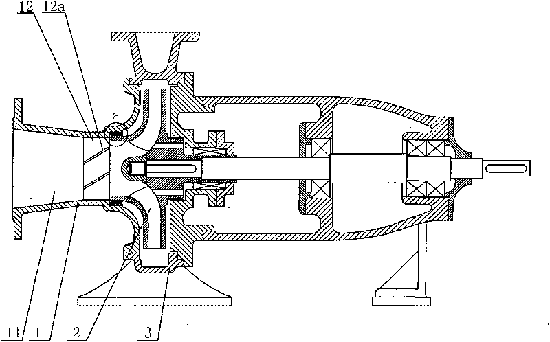
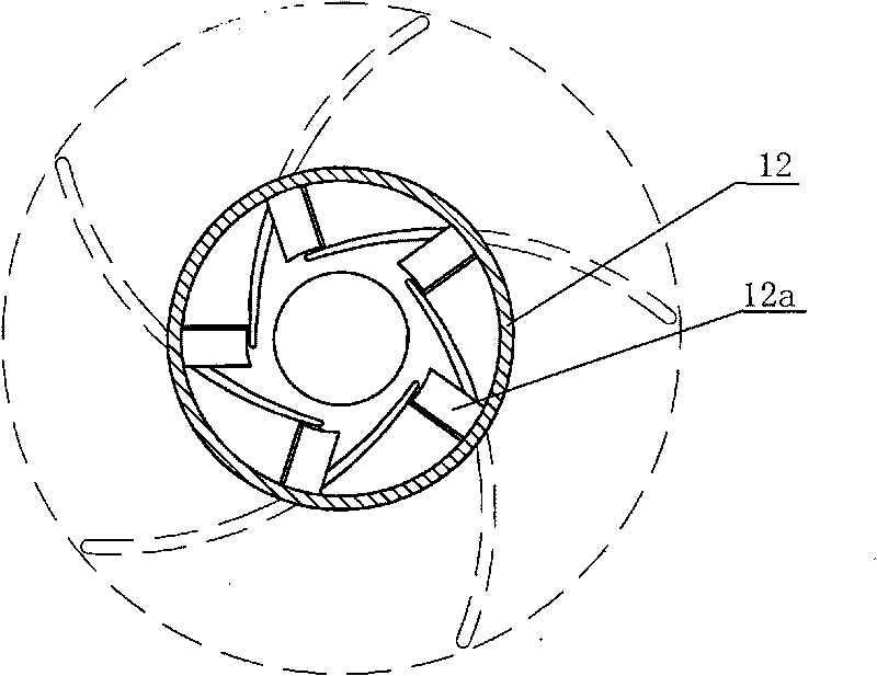
[0021] Reference Figure 1-7 , A new type of high-efficiency and energy-saving pump, including suction chamber 1, impeller 2, pump body 3, pump body sealing ring 4, impeller sealing ring 5 and other common components, the suction chamber 1 by the straight cone-shaped suction chamber 11 and its outlet end straight The pipe section 12 is composed of two parts, and the straight pipe section 12 is provided with an inclined partition plate 12a.

[0022] The inclination direction of the partition 12a is consistent with the rotation direction of the impeller 2.

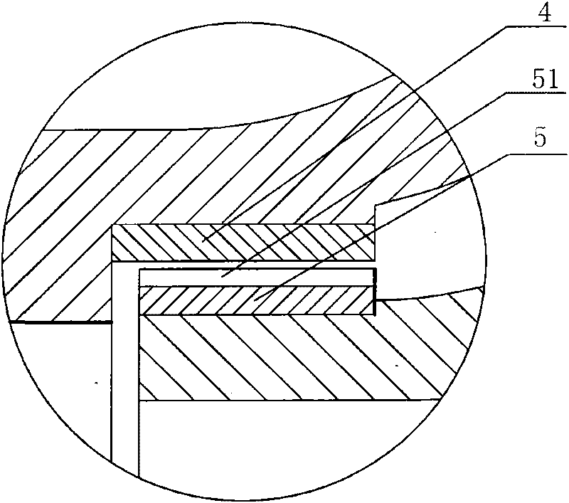
[0023] Diversion grooves 51 are evenly distributed on the outer surface of the impeller sealing ring 5 in the circumferential direction.

[0024] The pump body 3 is attached with an elongated tongue 31, and the small gap between the inner surface of the elongated tongue 31 and the outer circular surface of the impeller 2 generates greater resistance and forms a throttle arc surface 31a; The contour line of the partition tongue 31 is


PUM


Abstract

The invention discloses a novel high-efficient energy-saving pump, comprising a water sucking chamber, an impeller, a pump body, a pump body seal ring and an impeller seal ring, wherein the water sucking chamber is composed of a straight cone-shaped water sucking chamber and a straight tube section of the outlet end of the straight cone-shaped water sucking chamber; the straight tube section is internally provided with an inclined clapboard. The novel high-efficient energy-saving pump of the invention has the beneficial effects that the circumferential circulation exists in the liquid flow at the outlet of the water sucking chamber, the impact loss of the impeller inlet is reduced, and the pump efficiency is improved; the leakage rate of the gap between a seal ring and a lengthening cut-water is reduced, and the leakage lose is lowered; and the seal ring has good sealing performance and long service life, and is especially suitable for application occasions where conveying medium contains solid particles.

Description


Claims


Application Information

Patent Timeline
Owner ZHEJIANG UNIV OF TECH
Why Eureka
Try Eureka