Electric energy monitoring system

A monitoring system and electric energy technology, applied in the field of power system, can solve the problems of large error in analysis and calculation, inconvenience to find problems in time, inconsistent time of copying and reporting, etc., to achieve the effect of automation

Active Publication Date: 2010-07-07
CHINA SHENHUA ENERGY CO LTD +1
View PDF0 Cites 13 Cited by
  • Summary
  • Abstract
  • Description
  • Claims
  • Application Information

AI Technical Summary

Problems solved by technology

[0004] In the past, there were many problems in the analysis of manual copying, such as: long analysis period, inconvenient to find problems in time, resulting in large power loss; inconsistent copying time and errors in manual copying and entry, resulting in large analysis and calculation errors; many human factors, The work efficiency is low, and the power information cannot be reflected in time and accurately; the manual data needs to be entered into the computer for analysis,

Method used


Image

  • Electric energy monitoring system
  • Electric energy monitoring system
  • Electric energy monitoring system

Examples


Embodiment Construction

[0014] Electric energy monitoring is completed in three steps. The first step is to complete the data collection of the electric energy meter in the substation, and the data is established on the server to realize the preliminary analysis and assessment of electric energy; the second step is to complete the data collection of the substation, through the LAN or optical fiber The communication network is transmitted to the server to complete the assessment of the team's power consumption efficiency; the third step is to transmit the operation signal of the dispatch center to the server to realize the statistics and assessment of the power consumption status of each process.

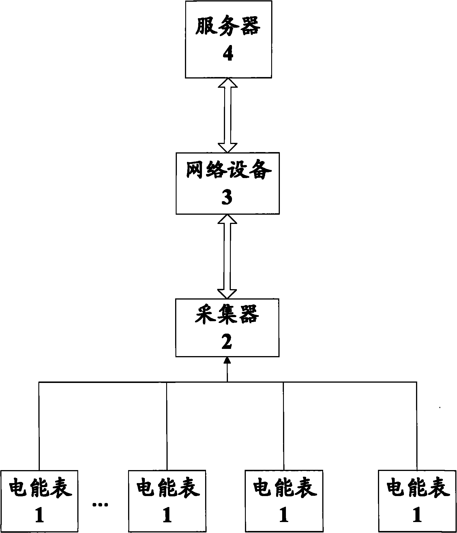
[0015] figure 1 It is a schematic structural diagram of an electric energy monitoring system in a preferred embodiment. The electric energy monitoring system of the present invention includes: an electric energy meter 1, a collector 2, a network device 3, and a server 4, wherein the electric energy meter 1 is


PUM


Abstract

The invention discloses an electric energy monitoring system, comprising an electric energy meter, a collector, a network apparatus and a server. The electric energy meter is used for detecting the electric energy data of each electric energy metering point; the collector is connected with the electric energy meter and used for collecting the electric energy parameter of each electric energy meter; the network apparatus is connected with the collector, and the electric energy data collected by the collector is transmitted to the server; and the server is used for receiving the electric energy data as well as calculating and processing the electric energy data. The electric energy monitoring system fully considers the real-time, the accuracy and the efficiency of the data collection, and uses an advanced hardware/software design scheme to realize automation, intelligent and networking for data collection analysis.

Description


Claims


Application Information

Patent Timeline
Owner CHINA SHENHUA ENERGY CO LTD
Why Eureka
Try Eureka